
Raspberry Pi Based Obstacle Avoiding Robot with Ultrasonic Sensor 11
[otw_is sidebar=otw-sidebar-1]In this article I will discuss the Raspberry Pi Based Obstacle Avoiding Robot with Ultrasonic Sensor and Python language. In the previous article I have discussed the interface of Ultrasonic sensor and the Raspberry Pi using the Python language. So this post will be oriented around how to use this Ultrasonic sensor and Raspberry Pi to make the Hurdle avoiding car.
After reading this post you will be able to understand the basics of the circuit included in the Project and also you will learn about the important libraries of Python in the Raspbian (recommended operating system) and how to use these libraries to write the code that can perform task in the physical world. So sit back keep reading and enjoy learning.
[otw_is sidebar=otw-sidebar-2]
Equipment Required of project:
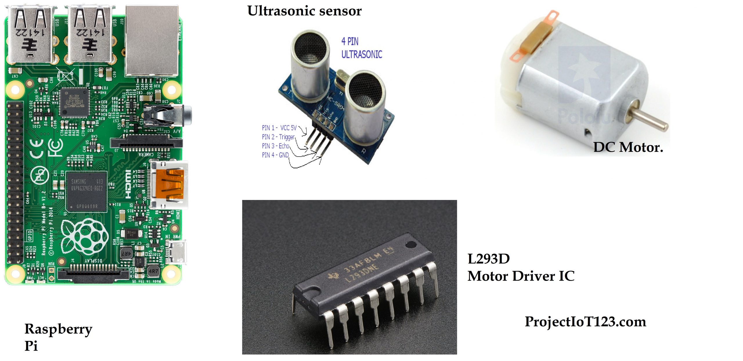
- You will need to have some of the equipment to be able to make this Project. The list of the important equipment needed for the Project is listed below:
- Raspberry Pi.
- Ultrasonic sensor.
- Motor driver.
- Jumper wires.
- Bread board or vero board as you wish.
- Car chassis.
[otw_is sidebar=otw-sidebar-3]
Project Overview:
The hurdle avoiding car we are considering in this post has the Raspberry Pi as its main controller. The ultrasonic connected to the Raspberry Pi will guide the autonomous vehicle to make turns and stop and reverse the direction etc. One of the very important components employed in the Project is the motor driver as we all know that the Raspberry Pi cannot supply as much current as required to drive the motor. So in order to be able to drive the motor using the Raspberry Pi the motor driver needs to be connected between the Raspberry PI and the motor to provide enough current to the motor to move the hurdle avoiding autonomous vehicle. So as a summary the hurdle avoiding autonomous vehicle based on the Raspberry Pi will be an important demonstration of the knowledge we have possessed in the previous posts. Without any delay let us dive deep into the Project.
Raspberry Pi, Ultrasonic sensor and the Python:
As described in the previous posts there are number of platforms for Programming the Raspberry Pi but the most popular is the Python IDLE which comes by default in the Raspbian for the Raspberry Pi. The library involved in the code for the Project is the GPIO.Rpi which is the Python library for programming the general purpose input / output pins of the Raspberry Pi. It comes installed by default in the newer versions of the Raspbian in case you do not have installed this library read my post on installing the library and then come here again. It is important that you have this library.
The ultrasonic sensor has four pins.
Vcc.
GND
Echo
Trigger.
The Vcc will be connected to the power supply and GND will be connected to the ground. The other two pins will be connected to the GPIO pins of the Raspberry Pi. Notice here that the Raspberry Pi GPIO pins are not configured as either I2C or SPI. This is the advantage of using the Ultrasonic sensor for the beginners’ tutorial. The way these data pins are connected to the Raspberry Pi will be clear when we write the code using the Python. In short one of the two pins through which the Ultrasonic sensor is connected will be serving as the input and the other pin as the output more about this will be discussed in the sections to follow.
Hardware of the Project:
Let us discuss the circuit configuration required in the project. Here I am assuming that you have all the equipment required and have already installed the library. The block diagram of the overall project is shown in the following image:
 As can be seen in the above picture that the Raspberry PI is connected to the Ultrasonic sensor and then it is connected to the motor driver which in turn connects to the motors. The ultrasonic sensor gives the data about the surroundings of the vehicle to the Raspberry Pi. The raspberry Pi then operates on the data by making the decisions which are governed by the code we will be writing in the next section. After operating on the data provided by the Ultrasonic sensor then the Raspberry Pi will give the commands to the motor driver which in turns moves the motors to change the directions of the Hurdle avoiding autonomous vehicle.
Important note:
[otw_is sidebar=otw-sidebar-3]
Before proceeding make sure which of your motor terminal polarity gives the clockwise rotation and vice versa.
Now let us connect the circuit like shown in the following picture.
 The Vcc pin of each of the component that is the Raspberry Pi, motor driver, ultrasonic sensor are connected to the common terminal, in the same way the ground of all the components are connected together. Now you need to configure the L293D motor controller IC in the way shown in the figure. If you are new using the L293D motor controller open its data sheet and notice which of the pin of the pin of the motor controller IC are connected respectively. Or you can see any of the tutorials on this IC. By the way it is not that difficult. The L293D motor controller IC will serve as the H-bridge topology in this circuit. Note that the pin number 11 and 13 are connected to the trigger pin and the Echo pin of the Ultrasonic sensor. The GPIO pins 32, 34, 36 38 and 40 are connected to the input pins of the motor driver IC. Then the output of the L93d motor controller IC are connected to the motors. The pin out of the L293D motor controller IC is shown in the following image to help you understand the above circuit.
Note that the above circuit is connected to the code written in the Python language. Now after you have wired the above diagram consider the code in the following section.
Python code for the Hurdle Avoiding car based on the Raspberry Pi:
In order to write the code for the Raspberry Pi in the python IDLE, you need to follow the following steps.
Step1:
Open the Python IDLE:
[otw_is sidebar=otw-sidebar-3]
Step2:
Now you can copy and paste the following code in the python IDLE:
import RPi.GPIO as GPIO
import time
GPIO.setwarnings(False)
GPIO.setmode(GPIO.BCM)
TRIG = 17
ECHO = 27
led = 22
m11=16
m12=12
m21=21
m22=20
GPIO.setup(TRIG,GPIO.OUT)
GPIO.setup(ECHO,GPIO.IN)
GPIO.setup(led,GPIO.OUT)
GPIO.setup(m11,GPIO.OUT)
GPIO.setup(m12,GPIO.OUT)
GPIO.setup(m21,GPIO.OUT)
GPIO.setup(m22,GPIO.OUT)
GPIO.output(led, 1)
time.sleep(5)
def stop():
print "stop"
GPIO.output(m11, 0)
GPIO.output(m12, 0)
GPIO.output(m21, 0)
GPIO.output(m22, 0)
def forward():
GPIO.output(m11, 1)
GPIO.output(m12, 0)
GPIO.output(m21, 1)
GPIO.output(m22, 0)
print "Forward"
def back():
GPIO.output(m11, 0)
GPIO.output(m12, 1)
GPIO.output(m21, 0)
GPIO.output(m22, 1)
print "back"
def left():
GPIO.output(m11, 0)
GPIO.output(m12, 0)
GPIO.output(m21, 1)
GPIO.output(m22, 0)
print "left"
def right():
GPIO.output(m11, 1)
GPIO.output(m12, 0)
GPIO.output(m21, 0)
GPIO.output(m22, 0)
print "right"
stop()
count=0
while True:
i=0
avgDistance=0
for i in range(5):
GPIO.output(TRIG, False)                 #Set TRIG as LOW
time.sleep(0.1)                                   #Delay
GPIO.output(TRIG, True)                  #Set TRIG as HIGH
time.sleep(0.00001)                           #Delay of 0.00001 seconds
GPIO.output(TRIG, False)                 #Set TRIG as LOW
while GPIO.input(ECHO)==0:              #Check whether the ECHO is LOW
GPIO.output(led, False)
pulse_start = time.time()
while GPIO.input(ECHO)==1:              #Check whether the ECHO is HIGH
GPIO.output(led, False)
pulse_end = time.time()
pulse_duration = pulse_end - pulse_start #time to get back the pulse to sensor
distance = pulse_duration * 17150        #Multiply pulse duration by 17150 (34300/2) to get distance
distance = round(distance,2)                 #Round to two decimal points
avgDistance=avgDistance+distance
avgDistance=avgDistance/5
print avgDistance
flag=0
if avgDistance < 15:      #Check whether the distance is within 15 cm range
count=count+1
stop()
time.sleep(1)
back()
time.sleep(1.5)
if (count%3 ==1) & (flag==0):
right()
flag=1
else:
left()
flag=0
time.sleep(1.5)
stop()
time.sleep(1)
else:
forward()
flag=0


Notice the libraries we have imported in the above code. One is the GPIO.Rpi and the other library is the time. Here I am just summarizing the code mentioned above:
First I have imported the libraries, then I have declared the variables to be used in the rest of the code, then I have defined the forward, backward, right and left movements. Then after this the Ultrasonic sensor is given the pulse. And then the calculation is performed to measure the average distance and in the last if else structure is used to make the commands.
That is all for now. I hope this article would be helpful for you. In the next post I will discuss the web server using the Raspberry Pi. Till then stay connected, keep reading and enjoy learning.
What if i need to use a 4-channel DC relay module instead of using L293 motor drive ” cause of the high current of my DC motor ??? Hi
Wow, marvelous blog structure! How lengthy have you
ever been blogging for? you make running a blog look easy.
The entire glance of your site is great, let alone the content material!
You can see similar here e-commerce
Wow, wonderful blog format! How lengthy have you ever been running a blog
for? you make blogging glance easy. The full look of your
web site is wonderful, let alone the content material!
You can see similar here najlepszy sklep
Wow, incredible weblog structure! How lengthy have
you ever been blogging for? you make blogging look easy.
The full glance of your web site is fantastic, let alone
the content material! You can see similar here sklep internetowy
Hello there! Do you know if they make any plugins to help with SEO?
I’m trying to get my blog to rank for some targeted keywords but
I’m not seeing very good results. If you know of any please share.
Cheers! You can read similar article here:
E-commerce
Wow, this article is fastidious, my younger sister is analyzing such things, so I am going
to inform her.
Visit my web page vpn 2024
What a information of un-ambiguity and preserveness
of valuable know-how about unexpected feelings.
Take a look at my blog … vpn coupon code 2024
Howdy! Do you know if they make any plugins to help with SEO?
I’m trying to get my website to rank for some
targeted keywords but I’m not seeing very good results.
If you know of any please share. Cheers! I saw similar art
here: GSA Verified List
Excellent pieces. Keep posting such kind of information on your site.
Im really impressed by your site.
Hey there, You have done a fantastic job. I will certainly
digg it and individually suggest to my friends.
I’m confident they will be benefited from this web
site.
Also visit my web blog vpn special code
WOW just what I was looking for. Came here by searching for vpn special coupon code 2024
special coupon
Wow, superb blog layout! How lengthy have you been running a blog for?
you make running a blog glance easy. The total glance
of your website is fantastic, let alone the content! You can see similar here sklep internetowy