
Raspberry Pi GPIO PINS with Stepper Motor using L298 Motor Controller 1
[otw_is sidebar=otw-sidebar-1]In this post I will discuss about how to interface the Raspberry Pi with the Stepper motor using the L298 Motor Controller. The Raspberry Pi can be used in different types of unmanned vehicle (UV) but to use Raspberry Pi in such robots we need to use some type of Motor controller because the Raspberry Pi cannot provide enough current to drive the motors. In order to drive the stepper motor we need to use the L298 motor controller for the sake of this post.
[otw_is sidebar=otw-sidebar-3]
Raspberry Pi GPIO PINS with Stepper Motor using L298 Motor Controller:
After reading this post you will learn about the stepper motor, the applications of the stepper motor, difference between the stepper, H-bridge topology and other types of motors and how to use Raspberry Pi to drive the stepper motors.
[otw_is sidebar=otw-sidebar-3]
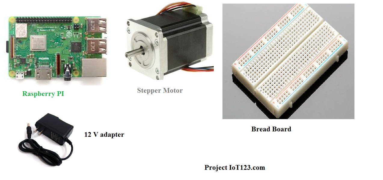
Equipment Required:
You will need the following stuff for this tutorial(Raspberry Pi GPIO PINS with Stepper Motor using L298 Motor Controller)
- Stepper motor.
- Raspberry Pi.
- Breadboard.
- Male-to-female connectors
- A 12V power supply.
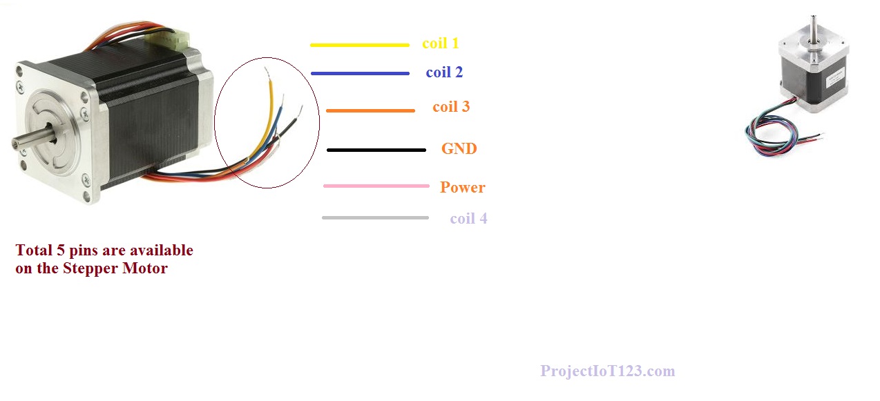 A stepper motor is also called a step motor; it is a DC brushless motor. As the name suggests a stepper motor is designed in such a way that the complete rotation of the motor is divided into the number of equal steps. It can be understand with an example that is consider that the complete rotation of the motor is 360 degrees now the stepper motor works in such a way that the entire 360 degrees rotation is divided into let us say 360 steps, so that when the stepper motor is commanded to move it can be operated to give one step which 1/360 degree rotation. Before anything you need to know whether you Stepper Motor is Unipolar or Bipolar. I am using the Bipolar Stepper Motor in this post.
There are different types of stepper motor:
- Permanent magnet stepper.
- Variable Reluctance Stepper.
- Hybrid Synchronous Stepper.
- The construction of the stepper motor is outside the scope of this post
.
Applications of the Stepper Motor:
[otw_is sidebar=otw-sidebar-3]
As can be seen in the above section that the stepper motor works in steps, so the stepper motor finds its application when the motion of the unmanned vehicle needs to be precise that is the movement in the forward, backward, right or left needs to be done by a certain degree. So stepper motors are very useful in:
CNC machine.
- X-Y plotter.
- Bomb disposal vehicle.
- Claw movement controller.
- Robotics.
- Military applications.
- Machine tools.
- Electronic watches and many more.
- Other Types of Motors:
- Servo Motors.
- DC motors.
- DC brushless motors and many more,
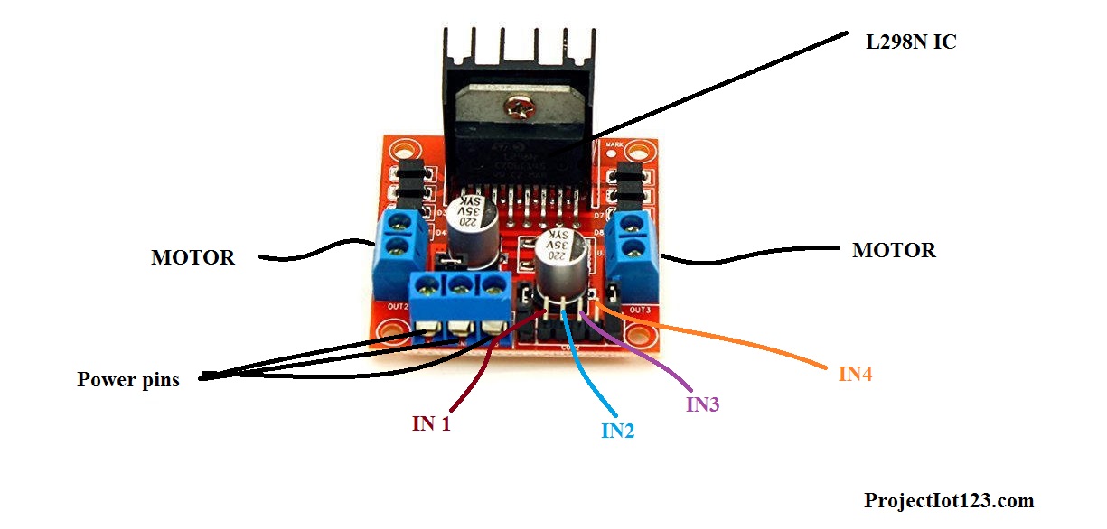 L298 motor controller comes in the modular form that is the IC and all the other components are populated onto the same Printed Circuit Board (PCB) and all you need to do is to connect the motors and the power supply to it via connectors. The L298 motor controller has four input pins which control the motor and its direction, two enable pins for controlling the speed via PWM (Pulse Width Modulation), two ports for connecting the motors, on-board voltage regulator and the power port to which 12 volt power supply is connected. This can be shown in the following image.
L298 Motor Controller Topology:
The L298 motor controller has the topology of the H-bridge circuit. The H-Bridge topology is very important in the motor controller applications as it has the capability of controlling the direction of rotation of the motor with the 5 V signaling technique as common in embedded controller. The following image clarifies the concept behind the L298 motor controller.
Raspberry Pi and Stepper Motor:
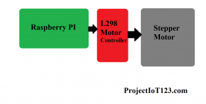
As clear that the stepper motor can be interfaced with any controller you want through the motor controller but the reason for using the Raspberry Pi to control the stepper is its high computational power that makes it suitable for self-learning robots, unmanned vehicles based on the Artificial Intelligence algorithms and those robots utilizing the Image Processing and the computer vision algorithms. So it becomes important one know how the Raspberry Pi can be used to control the Stepper Motor to carry out these important applications. The block diagram of the Raspberry PI and the Stepper Motor is shown in the following image:
 Raspberry Pi GPIO Circuit Overview:

The input pins of the L298 motor controller are connected to the General Purpose Input / Output pins of the Raspberry Pi, the General Purpose Input / Output pins gives the proper signal according to the program written in Python language to control each movement of the Stepper Motor. The Python script tell tells the Stepper motor when to move and how much to move and it will dos so using the Raspberry GPIO pins. Notice that to use the GPIO pins we will only need the GPIO python library and nothing else. I have already discussed the installation of the GPIO Python library in the Raspberry PI in my previous posts. You have to install this library to let the Raspberry Pi control the Stepper Motor. The connection between the Raspberry Pi and the Stepper motor is shown in the following image.
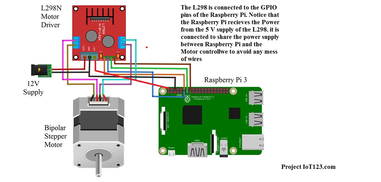 The 12 volt power supply is connected to the L298 motor controller, the motor controller has on board voltage regulator which converts the 12V to the 5 V so you can connect the Raspberry Pi power pins to the 5V supply from the L298 motor controller as shown in figure above.
Programming the Raspberry PI for Stepper Motor:
Let us know how to write the code for the Raspberry Pi to control the stepper. We will be writing the code in Python as it is one of the most programming platform for the Raspberry Pi. Follow the following simple to be able to write the code in Python language.

Step1:
[otw_is sidebar=otw-sidebar-1]
First of all open the Python IDLE.
Step2:
You can copy and paste the following code in the Python IDLE.
import RPi.GPIO as GPIO
import time

out1 = 13
out2 = 11
out3 = 15
out4 = 12

i=0
positive=0
negative=0
y=0

GPIO.setmode(GPIO.BOARD)
GPIO.setup(out1,GPIO.OUT)
GPIO.setup(out2,GPIO.OUT)
GPIO.setup(out3,GPIO.OUT)
GPIO.setup(out4,GPIO.OUT)

print "First calibrate by giving some +ve and -ve values....."

try:
while(1):
GPIO.output(out1,GPIO.LOW)
GPIO.output(out2,GPIO.LOW)
GPIO.output(out3,GPIO.LOW)
GPIO.output(out4,GPIO.LOW)
x = input()
if x>0 and x<=400:
for y in range(x,0,-1):
if negative==1:
if i==7:
i=0
else:
i=i+1
y=y+2
negative=0
positive=1
#print((x+1)-y)
if i==0:
GPIO.output(out1,GPIO.HIGH)
GPIO.output(out2,GPIO.LOW)
GPIO.output(out3,GPIO.LOW)
GPIO.output(out4,GPIO.LOW)
time.sleep(0.03)
#time.sleep(1)
elif i==1:
GPIO.output(out1,GPIO.HIGH)
GPIO.output(out2,GPIO.HIGH)
GPIO.output(out3,GPIO.LOW)
GPIO.output(out4,GPIO.LOW)
time.sleep(0.03)
#time.sleep(1)
elif i==2:
GPIO.output(out1,GPIO.LOW)
GPIO.output(out2,GPIO.HIGH)
GPIO.output(out3,GPIO.LOW)
GPIO.output(out4,GPIO.LOW)
time.sleep(0.03)
#time.sleep(1)
elif i==3:
GPIO.output(out1,GPIO.LOW)
GPIO.output(out2,GPIO.HIGH)
GPIO.output(out3,GPIO.HIGH)
GPIO.output(out4,GPIO.LOW)
time.sleep(0.03)
#time.sleep(1)
elif i==4:
GPIO.output(out1,GPIO.LOW)
GPIO.output(out2,GPIO.LOW)
GPIO.output(out3,GPIO.HIGH)
GPIO.output(out4,GPIO.LOW)
time.sleep(0.03)
#time.sleep(1)
elif i==5:
GPIO.output(out1,GPIO.LOW)
GPIO.output(out2,GPIO.LOW)
GPIO.output(out3,GPIO.HIGH)
GPIO.output(out4,GPIO.HIGH)
time.sleep(0.03)
#time.sleep(1)
elif i==6:
GPIO.output(out1,GPIO.LOW)
GPIO.output(out2,GPIO.LOW)
GPIO.output(out3,GPIO.LOW)
GPIO.output(out4,GPIO.HIGH)
time.sleep(0.03)
#time.sleep(1)
elif i==7:
GPIO.output(out1,GPIO.HIGH)
GPIO.output(out2,GPIO.LOW)
GPIO.output(out3,GPIO.LOW)
GPIO.output(out4,GPIO.HIGH)
time.sleep(0.03)
#time.sleep(1)
if i==7:
i=0
continue
i=i+1

elif x<0 and x>=-400:
x=x*-1
for y in range(x,0,-1):
if positive==1:
if i==0:
i=7
else:
i=i-1
y=y+3
positive=0
negative=1
#print((x+1)-y)
if i==0:
GPIO.output(out1,GPIO.HIGH)
GPIO.output(out2,GPIO.LOW)
GPIO.output(out3,GPIO.LOW)
GPIO.output(out4,GPIO.LOW)
time.sleep(0.03)
#time.sleep(1)
elif i==1:
GPIO.output(out1,GPIO.HIGH)
GPIO.output(out2,GPIO.HIGH)
GPIO.output(out3,GPIO.LOW)
GPIO.output(out4,GPIO.LOW)
time.sleep(0.03)
#time.sleep(1)
elif i==2:
GPIO.output(out1,GPIO.LOW)
GPIO.output(out2,GPIO.HIGH)
GPIO.output(out3,GPIO.LOW)
GPIO.output(out4,GPIO.LOW)
time.sleep(0.03)
#time.sleep(1)
elif i==3:
GPIO.output(out1,GPIO.LOW)
GPIO.output(out2,GPIO.HIGH)
GPIO.output(out3,GPIO.HIGH)
GPIO.output(out4,GPIO.LOW)
time.sleep(0.03)
#time.sleep(1)
elif i==4:
GPIO.output(out1,GPIO.LOW)
GPIO.output(out2,GPIO.LOW)
GPIO.output(out3,GPIO.HIGH)
GPIO.output(out4,GPIO.LOW)
time.sleep(0.03)
#time.sleep(1)
elif i==5:
GPIO.output(out1,GPIO.LOW)
GPIO.output(out2,GPIO.LOW)
GPIO.output(out3,GPIO.HIGH)
GPIO.output(out4,GPIO.HIGH)
time.sleep(0.03)
#time.sleep(1)
elif i==6:
GPIO.output(out1,GPIO.LOW)
GPIO.output(out2,GPIO.LOW)
GPIO.output(out3,GPIO.LOW)
GPIO.output(out4,GPIO.HIGH)
time.sleep(0.03)
#time.sleep(1)
elif i==7:
GPIO.output(out1,GPIO.HIGH)
GPIO.output(out2,GPIO.LOW)
GPIO.output(out3,GPIO.LOW)
GPIO.output(out4,GPIO.HIGH)
time.sleep(0.03)
#time.sleep(1)
if i==0:
i=7
continue
i=i-1

except KeyboardInterrupt:
GPIO.cleanup()
Notice the library we have imported on the above code, this library (RPi.GPIO) is important to install otherwise your set up will not work.
[otw_is sidebar=otw-sidebar-3]
That is all for now I hope this article would be helpful for you. In the next article I will discuss some more interesting applications of the Raspberry Pi till then stay connected, keep reading and enjoy learning.
One Comment
Trackbacks and Pingbacks
[…] Raspberry Pi GPIO PINS with Stepper Motor using L298 Motor Controller […]