
Operational Amplifier Active High Pass Filter 2
[otw_is sidebar=otw-sidebar-1]
In this post I will discuss the implementation of the Operational Amplifier as the active high pass filter. In the previous post I have discussed the Operational Amplifier as the Summing Amplifier and we learned there that the Operational Amplifier can be configured to perform a lot of operations and the operation that the operational amplifier performs depends upon the feedback configuration. The feedback network for the Operational Amplifier can be purely resistive or a combination of resistors, capacitors and inductors. Here the discussion will be focused on the Operational Amplifier as the high pass filter in which we will design the unique circuit for feedback network.
After reading this post you will learn about the Operational Amplifier implementation as the Active Filter, various types of filter topologies, filter topologies implementation using the Operational Amplifier, low pass filter, high pass filter, band-pass filter and band-stop filter. So sit back, keep reading and enjoy learning.
Filters:
[otw_is sidebar=otw-sidebar-3]
Before diving deep into the discussion of the Operational Amplifier as the filters let us discuss what basically the Filter circuits are. As the name implies the filter is type of electronic circuit that allows certain frequencies in the signals to be passed while attenuating other unwanted frequencies. The filtering can be thought as the signal processing in which the signal is processed so that the signal contains the desired frequencies and depleted of all the unwanted frequencies. Filters can be classified into two classes according to the design technology point of view:
- Active filters.
- Passive Filters.
The classification of the filters according to the way it filters the signal leads to two categories:
- Analog Filter.
- Digital Filter.
Most of you must have the knowledge of the analog filters in which we design the analog circuit with analog design principles and this type of filter acts on the analog signals but the process of filtering can also be done in the digital domain in which the signal to be filtered is converted to the digital signal using the analog to digital converter and then the digital signal processor runs the effectively designed algorithm to filter the signal. After filtering in the digital domain the digitized signal is converted back to the analog signal using the Digital to Analog converter (ADC). The discussion on the digital filter is beyond the scope of this post and we will stick here to the active high pass filter using the Operational Amplifier.
Let us now see what are the Active filters?
Active Filters:
For the sake of relevance I will stick to the Active Filters only here. The Active Filters are the type of filters which are implemented using at least active component which in our case is the Operational Amplifier. The active filter can be designed to allow the higher frequencies to be passed through it while attenuating the lower frequencies; this type of filter is called the high pass filter. In the similar way the filter can also be designed to pass the low frequencies through it while attenuating the higher frequencies; these types of filters are called the low pass filters. Following the same context band-pass filters allow the certain frequencies while attenuating the upper and lower frequencies of the band that ought to be passed and opposite in the case for band-stop filter which attenuates the particular set frequencies while allowing all the frequencies to be passed.
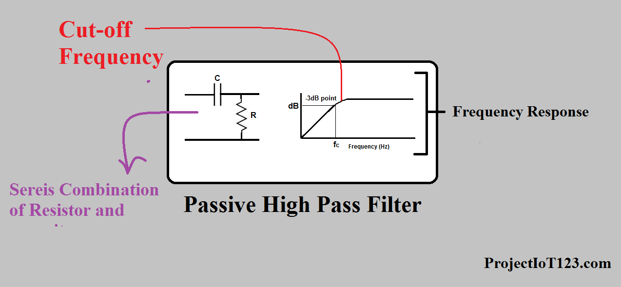
On the other hand the passive filters are based on the resistors, capacitors and inductors. I will not go deep into the discussion on the passive filter however the high pass passive filter looks like the one in the following image:
Cut-off frequency:
[otw_is sidebar=otw-sidebar-3]
An important consideration while designing the filter of any the above mentioned types is the cut-off frequency. The cut-off frequency of the filter can be designed as the threshold for the filter that is in case of low pass filter cut-off frequency is that above which the filter will not allow the signal to pass. In the similar way cut-off frequency for the high pass filter is that frequency below which no signal can pass through the filter. As you must have figured out that the band-stop and band-pass filters have two frequencies one is called the upper cut-off frequency and the other is called the lower cut-off frequency. The performance of the filter is determined by how sharp the cut-off frequency is for the filter.
Operational Amplifier and active filters:
As mentioned in the above section that the Operational Amplifier is one of the most popular devices among the analog engineers because of its diverse applications, among these applications one of the most common and widely used is active filters. Operational Amplifier can be configured to function as low pass filter, high pass filter, band pass filter or band stop filter. The Operational Amplifier acting as one of these filters depends upon the feedback network. The point I am trying to make here is that the Operational Amplifier feedback network can be altered to function as any one of these filters. Let us discuss the Operational Amplifier active filters in some detail.
Note:
An important consideration while designing the filter based on the Operational Amplifier is that if you use the Operational Amplifier in the differential input mode and additional advantage of the common mode rejection will be used in the filter. It can be understand by this. As most of you must know that the signal wire carry the Electromagnetic Interference which disturbs the original signal but however this Electromagnetic Interference (EMI) noise is present on both of the lines of the signal and the Operational Amplifier in the differential mode does allow this noise to passed because it passes and amplify only the difference of the signals at the inverting and non-inverting input terminals. So besides the High pass filtering and advantage of EMI noise filtering is done by the Operational Amplifier in the differential input mode. The idea of the differential signaling can be visualized by the image shown below:
[otw_is sidebar=otw-sidebar-2]
Operational Amplifier High Pass Filter:
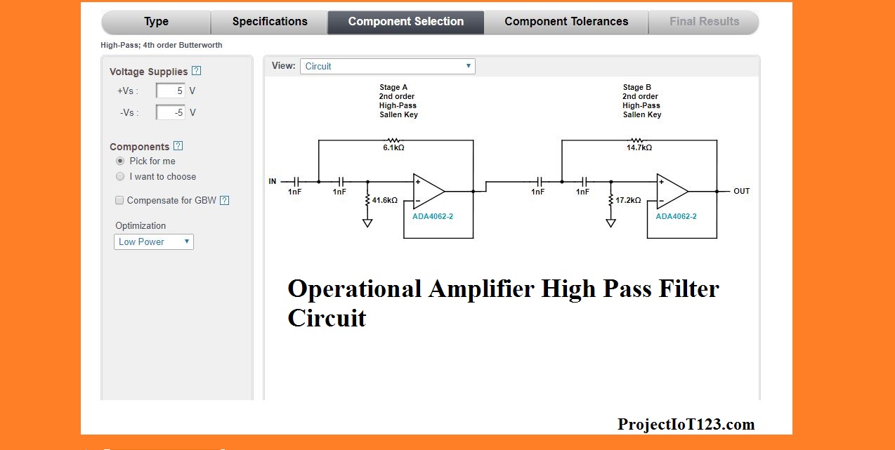
As mentioned in the above section that the feedback network of the Operational Amplifier can be designed to manipulate it as the High pass filter. The High pass filters are of two types with respect to the design point of view. One is the passive high pass filter which can be implemented using resistors, capacitors or inductors and the second is the active high pass which is implemented using the Operational Amplifier or any other active component by the way the Operational Amplifier is the most popular for this purpose.
The cut-off frequency of the high-pass filter is the frequency below which the filter will attenuate all the frequencies considerably. In the Operational Amplifier based high pass filter the cut-off frequency can be customized by choosing the appropriate values of the resistor and capacitors in the feedback network of the Operational Amplifier. The circuit implementation of the Operational Amplifier based High pass filter is shown below:
The frequency response of the Operational Amplifier high pass filter is shown in the following figure:
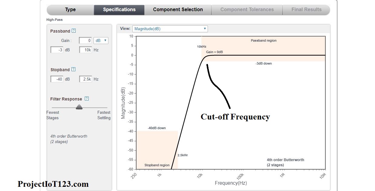
As you must have noticed that the above circuit for the high pass filter is designed to have the cut-off frequency of 40 kilo Hertz. All the frequencies below the 10 KHz have been attenuated considerably and the frequencies above this cut-off have been passed without attenuation.
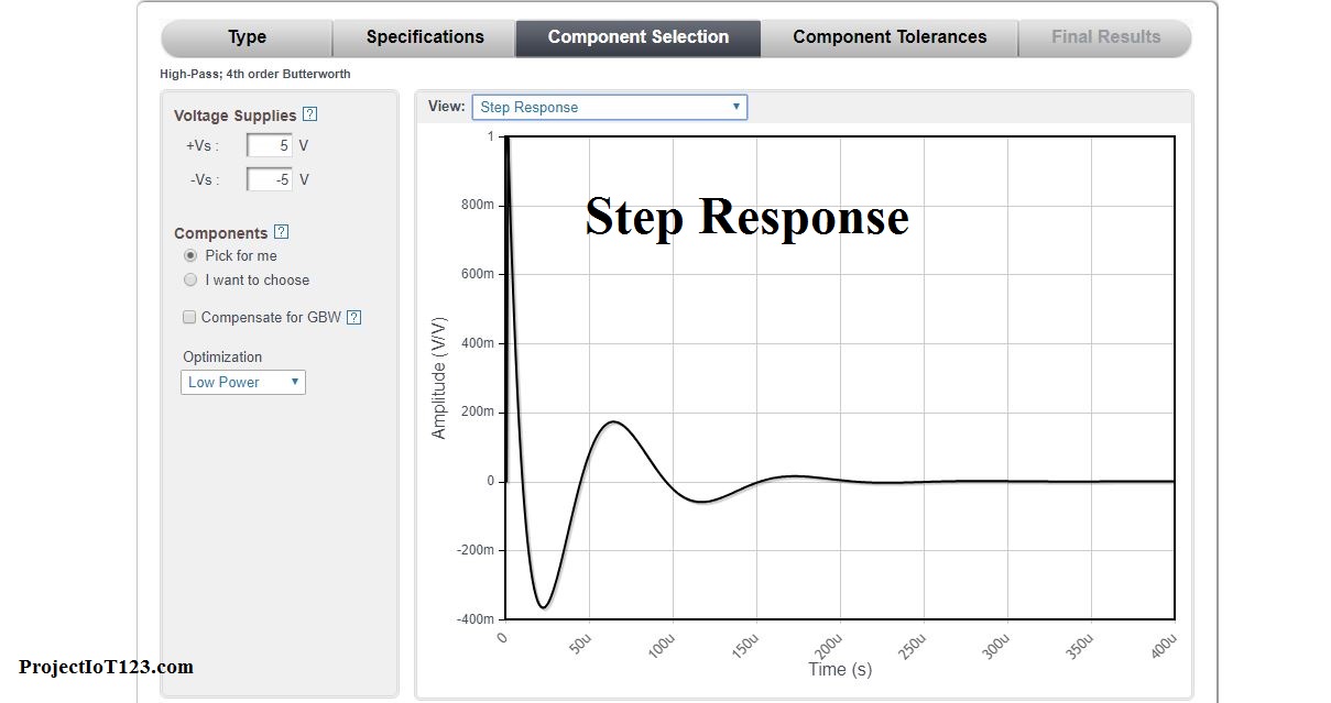
The step response of the above designed circuit is shown below:
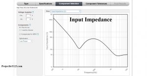
The input impedance of the above circuit corresponding to the frequency is given below:
 Frequency Response:

While studying the filters you will continuously read the term “Frequency Response” so it is recommended that you must know the meaning of the frequency response of the filters or any other system. As the name implies the frequency response of the system gives the knowledge about the relationship between the input and output from the frequency point of view. That is the frequency response diagram of the filter shows the relation between the input frequencies to the filter and the magnitude of the output signal in decibel. That is the frequency response of the filter shows the magnitude in decibel of the output signal corresponding to the frequency applied at the Input of the Filter.
That is all for now I hope this article will be helpful for you. In the next post I will come up with more interesting applications of the Operational Amplifier in the coming posts. Till then stay connected, keep reading and enjoy learning.
Wow, incredible blog layout! How lengthy have you been blogging
for? you make running a blog look easy. The whole glance of your site
is excellent, as neatly as the content material!
You can see similar here e-commerce
Hi! Do you know if they make any plugins to help with SEO?
I’m trying to get my website to rank for some targeted keywords
but I’m not seeing very good success. If you know of any please share.
Cheers! I saw similar article here: List of Backlinks