
Vibration Sensor Simulation in Proteus Leave a comment
[otw_is sidebar=otw-sidebar-1]In this post I will discuss about the simulation of the Vibration Sensor in Proteus. In the last post I have discussed about the L298 motor driver and its simulation Proteus. I have also discussed about the other commonly known sensors and their simulation in Proteus. The simulation of the commonly known actuators such as the Relay module has also been discussed. This post will be oriented around the discussion on the Vibration sensor and also its simulation with Arduino in Proteus will also be discussed.
[otw_is sidebar=otw-sidebar-2]
Vibration Sensor Simulation in Proteus:
After reading this post the reader will be able to learn about the Vibration sensor, working and principle of the Vibration Sensor, simulation model and simulation model of the Vibration sensor, interfacing of the Vibration with Arduino and finally the simulation of Vibration Sensor in Proteus. So sit back, keep reading and enjoy learning.
Vibration Sensor:
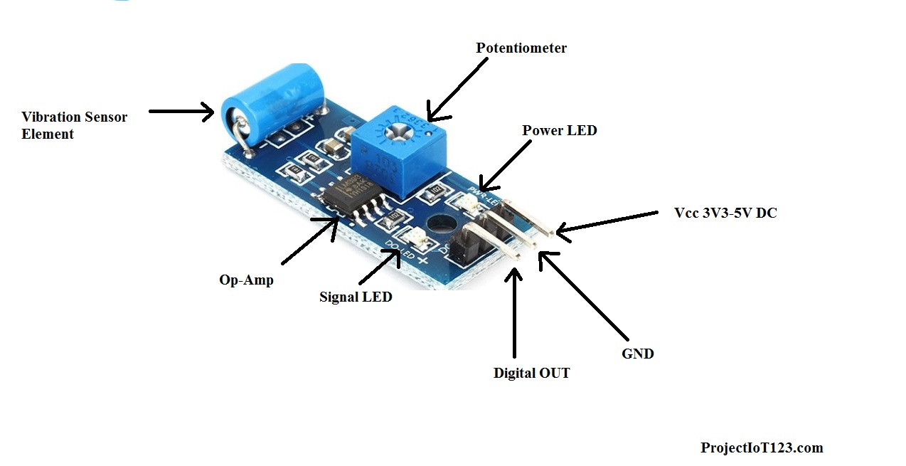
Before diving deep into the discussion on the simulation of the Vibration sensor let us first learn what the Vibration sensor is and how it works? Vibration sensor as the name implies is the type of sensor that is used to measure the vibration of the body on which it is installed. Practically it is quite difficult to measure the Vibration of the body as there are a lot of chances of false reading. Before installing the Vibration Sensor on the body whose vibration is to be measured the Vibration Sensor should be properly calibrated to avoid the false readings. The vibration sensor is available in the market in the modular form as shown in the following figure:
[otw_is sidebar=otw-sidebar-3]
The core of the Vibration sensor is the element that is used as the Vibration sensor element. The circuit following the Vibration sensor element is basically the signal conditioning circuit which makes the signal from the element to be used for practical purposes. The potentiometer at the Vibration sensor is used to calibrate the sensor. The potentiometer adjusts the sensitivity of the Vibration sensor module to avoid the false readings. The Operational Amplifier here is used as the comparator which compares the electrical signal from the Vibration sensor element and the reference of the Potentiometer. So it should be noted here that the potentiometer actually adjusts the voltage at the input terminal of the operational amplifier and this voltage acts as the reference with which the signal from the vibration sensor is compared.
Working of the Vibration Sensor:
As we noted in the above section that the potentiometer adjusts the value of the voltage at the input terminal of the Operational Amplifier to be compared with the voltage signal from the vibration sensor element. So if the voltage of the Vibration sensor element is greater in magnitude as compared to the voltage provided by the Potentiometer then the digital output of the Vibration sensor module goes HIGH. This indicates the presence of some sort of vibration. On the other hand if the vibration is not present on the body on which the module is installed then there will be no output at the out pin of the sensor. The signal LED present on board represents the HIGH and LOW signal indicating the Vibration.
Vibration Sensor Library for Proteus:
After you have learned the basics of the Vibration sensor and its working it is now time to simulate the behavior of the Vibration sensor in Proteus. It is important here to mention that it is always beneficial that you simulate the behavior of the system before actually implementing its hardware in real world. With the help of simulation the designer can look for the glitches in coding of the controller and the error in the circuit. Thus the simulation can save both time and money. It is important here to note that if you want to simulate the behavior of any system it is crucial that the simulation model of all of the components that are used in the circuit should be present in the library of the software. If the simulation model is not present in the library of the software the software will unable to imitate the behavior of the circuit. The simulation model of the Vibration sensor is not present in the library of the Proteus so we need to download it first. After downloading the library it is now time to place the files containing the simulation model of the Vibration sensor in the library of the Proteus. If you do not know about how to place the files containing the simulation model of the sensor please go through my post on Ultrasonic sensor. I have discussed in detail there. After placing the files in the library of the Proteus follow the following simple steps to simulate the Vibration sensor in Proteus.
[otw_is sidebar=otw-sidebar-3]
Step1:
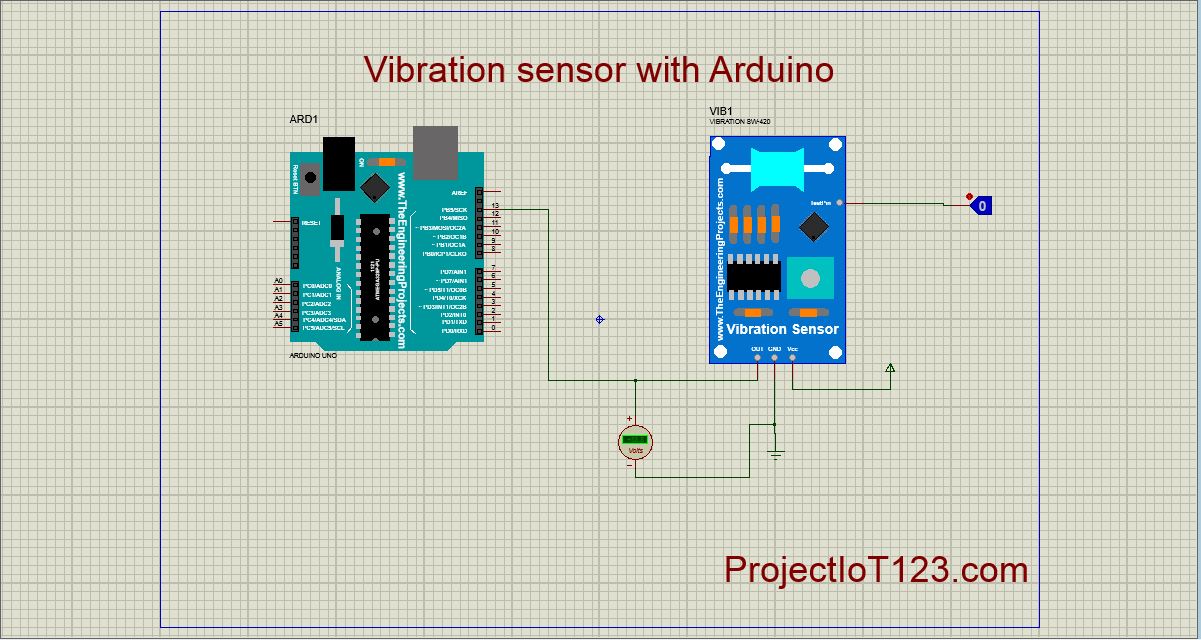
Place all the components that are to be used in the workspace of the Proteus as shown in the following figure:
Step2:
Now connect the circuit as shown in the following figure:
Note in the above circuit that the simulation symbol of the Vibration sensor has one extra pin called the TEST PIN to which the logic toggle is connected. This pin is used to imitate the presence of the Vibration.
Step3:
Attach the simulation file to the symbol of the Vibration Sensor as shown in the following figure:
The pop up window appear by double clicking the symbol in the workspace.
Step4:
Now attach the HEX file of the code in the Proteus to the Arduino. This HEX file provides the instruction about the behavior of the Arduino in the simulation. It can be seen in the following figure:
This pop up window also appears by double clicking the Arduino. Browse for the HEX file of the code and attach that to the Arduino.
[otw_is sidebar=otw-sidebar-3]
Step5:
The circuit is ready to simulate. Hit the simulation button and the animation will begin showing the simulation.
That is all for now I hope this post will be helpful for you. In the next post I will come up with more interesting applications of the simulation of Proteus. Till then stay connected, keep reading and enjoy learning.