
Allegro Use Add Connect Tool 57
[otw_is sidebar=otw-sidebar-1]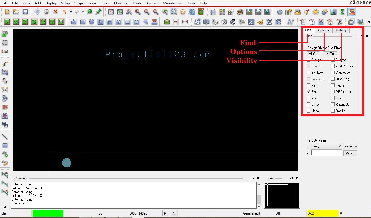 Hey guys!I hope you all are good, in the previous tutorial I have discussed the brief introduction of the Allegro PCB designer software and few commands used for routing, I have discussed in detail the “Add Connect” command, in this tutorial I will further explain about how to adjust the bent angle and width of the Cline. Before discussing that let us first learn about another window in the Allegro PCB Designer GUI as shown in the following image:
Introduction to Allegro PCB Designer (Part 2)
This window consists of three windows named 1) Find 2) Options 3) Visibilty. While routing the PCB at the beginners’ level (single layer board) only “Find” and “Options” window are used. Let us discuss “Find” window first.
The “Find” window consists of the various elements in the checklist as shown in the following image:
 After the “Add Connect” command is activated the software will be able to pick only that element which has been checked in the “Find Window”. For example as shown in the above image check box of the “Pins” is checked therefore the software can only begin routing from the pin of any electronic component. There are some situations where we need to start routing from a particular point on the Cline, the software can begin routing from any point on the Cline if and only if check box of the “Cline” is checked shown in the above image. Different command depends on different elements in the “Find” window, for example the “Text” element is of no use for “Add Connect” command.
Note:
Cadence Allegro Tutorials
| LIST OF Cadence AllegroTurorials | Names |
| Tutorial # 1 | Introduction to Allegro PCB Designer |
| Tutorial # 2 | Allegro Use “Add Connect Tool” |
| Tutorial # 3 | Allegro Use “Slide Tool” |
| Tutorial # 4 | Allegro Use “Hilight & Dehilight Tool” |
| Tutorial # 5 | Allegro Use “Show Measure & Grid” |
| Tutorial # 6 | Introcution to Nets in Allegro |
| Tutoiral # 7 | Introcution to Stackup in Allegro |
| Tutorial # 8 | Introcution to Copper Shapes in Allegro |
| Tutorial # 9 | Introduction Vias and GND Plane in Allegro |
ALL Orcad Allegro Tutorial for Beginner Ask free to Question us
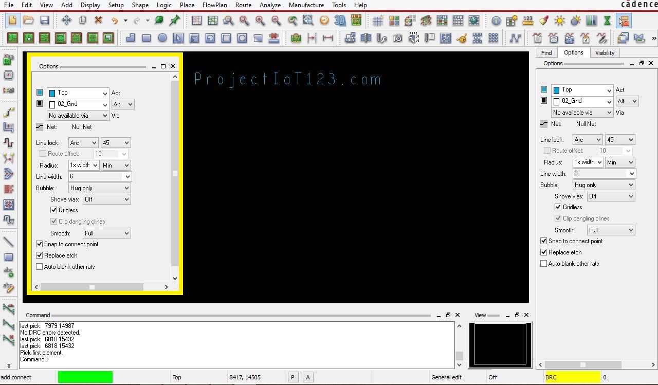
Another important window is “Options” this window consists of various options for altering the properties of the command. Options related to the command can be seen on the “Options” window only when the command is active. So left click on the “Add Connect” command, then open the “Options” window to view the options as shown in the following image. highlighted by the yellow box.
 We will discuss only the line width and line lock options shown above. Click on the line width option and enter width, the width of the Cline (copper etch) changes accordingly as shown in the following image.
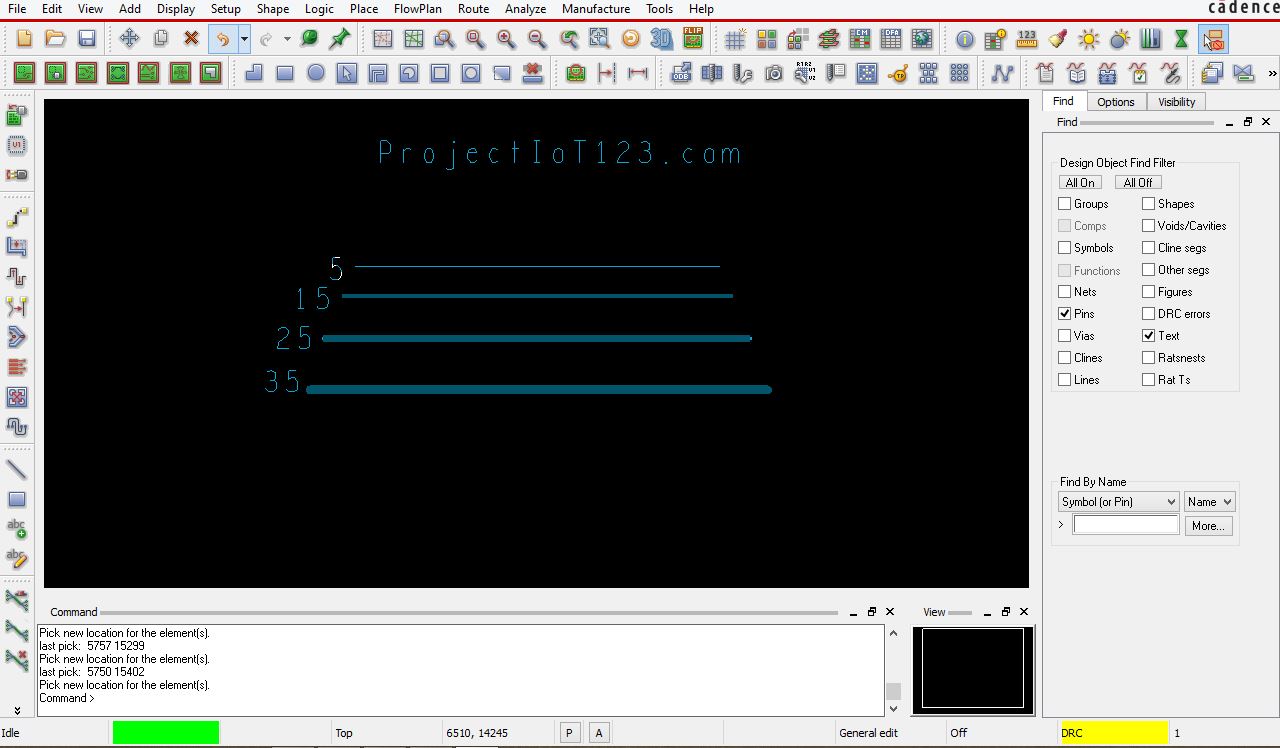 Line widths are mentioned corresponding to the Cline shown in the above image. Line widths are selected according to the electrical characteristics of the signals and requirements of the clients.
Now let us discuss the bent angle of the Cline. See the angle option next to the line lock option. The bent angle of the 45 degrees is as shown in the following figure.

[otw_is sidebar=otw-sidebar-3]
The bent angle of 90 degrees is selected as shown in the following image:
[otw_is sidebar=otw-sidebar-2]
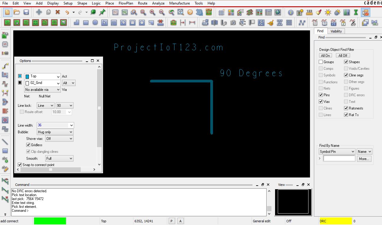
Thus in this way we can alter the width and bent angle of the Clines (copper etch).
[otw_is sidebar=otw-sidebar-3]
That is all for now, I hope this tutorial would be helpful for you, in the next tutorial I will discuss about the “Slide’ command. Till then stay connected, keep reading and enjoy learning.
Hi projectiot123.com
We noticed your website projectiot123.com is only listed in 12 out of 2500 directories.
This has a severe impact on your online global presence.
You can get listed in all 2500 directories for a once off fee of $99
Come visit us on https://projectiot123.companyregistar.org/projectiot123.com
The average viewer watches a video for only 12 seconds…this new tech rewards viewers for watching your entire video. GAMIFYING your Youtube video is changing the way companies market.
As seen on CBS, NBC, FOX, and ABC.
Shoot me an email or skype msg below to see if you qualify for a free GAMIFICATION of your video.
Jordan
email: gamifyvideo@gmail.com
skype: live:.cid.d347be37995c0a8d
Do you want to increase your domain authority? I will increase Moz Domain Authority 30+ & Ahref Domain Rating upto 50+ in just 7 days!
✔️ Google will love your site.
✔️ No spam
✔️ Fast Indexing.
✔️ Ranking Fast!
✔️ Extra boost on other metrics as well.
✔️ Permanent links
✔️ 100% white hat and safe backlinks.
✔️ All backlinks are Dofollow
The cost is MOZ DA 30+ & Ahref DR 50+ is $35. Delivery – 7-10 Days.
For more information please visit – https://cutt.ly/da-dr-50
Use coupon 15OFF – for $15 off.
Regards,
Claim your Reputation Video at no cost to you! Watch as we transform your exceptional 5-star reviews into captivating SEO content, propelling your visibility on Google’s front page. Claim your free video here: getyourfreereviewvideo.info
Struggling to Launch Your Online E-commerce Store?
Missing out on potential sales and customers? Building a successful eCommerce site can be complex and time-consuming.
Transform Your Business with Expert eCommerce Development at affordable prices!
Benefits:
✅ Customized Online Stores
✅ Seamless User Experience
✅ Boosted Sales and Conversions
Ready to create an E-Commerce store? Start Today!
https://outsource-bpo.com/website/?src=m14projectiot123.com
Don’t let eCommerce challenges hold you back. Launch a powerful online store with our expert eCommerce development services!
Is Your Website Not Ranking In Google?
Losing potential customers to competitors? Your website’s low rankings are costing you valuable leads and revenue.
Boost Your Rankings with Monthly SEO Services!
Benefits:
✅ Increase Search Engine Rankings
✅ Drive Targeted Traffic
✅ Boost Conversions
✅ 4x Profits
Transform Your Business Today!
https://alwaysdigital.co/la/?src=m14projectiot123.com
Are you okay running your business without much funds? This could slow down growth and delay returns on your business.
Now you have the Opportunity to Fund your Busineses and Projects without stress and without the burden of repayment as our interest in first for the growth of your business and projects, and for your to arrive at your desired business goals and dreams.
Take advantage of our Funding opportunity and get funded on your business and Projects within days and have an ample number of years/Loan Term Period which gives you time to grow and achieve your business goals.
Give us a call on:
+852 3008 8373,
or write us at:
info@capitalfund-hk.com
Hi,
If you need business financing fast, our fintech solution (2,000 Trust Pilot 5-Star reviews), analyzes the top 75+ lenders to find the perfect loan for YOUR business. Your personal concierge will generate three offers based on your needs with fast approvals & funding in 48 hours (no hard credit pull!).
Click here to learn how easy it is: https://cli.re/145Qx4
Thanks!
Steve
Struggling to Rank your Website In Google? Imagine your website buried in search results, missing out on valuable leads and potential customers.
Propel Your Business to New Heights with Monthly SEO! Top Rankings, Increased Traffic, Business Growth and Profit.
Experience the transformation. Rank your website on the first page, attracting targeted traffic, and converting visitors into loyal customers.
Introducing Out Monthly SEO – Your Gateway to Online Success!
✅ Tailored Strategies: Our Monthly SEO adapts to your business needs.
✅ Proven Results: Check our success stories for real transformations.
✅ Start Today: Elevate your online presence with a click.
Ready to See Your Website Rank? – https://digitalpromax.co/?src=m24projectiot123.com
GAMIFY your videos and get viewers to happily give you their email and phone number.
There is no other tech like this..it’s the next big thing. As seen on CBS, NBC, FOX, and ABC.
See if you qualify for a free GAMIFICATION of your video.
Contact me via my email or skype below for more details
Robert
email: gamifyvideo@gmail.com
skype: live:.cid.d347be37995c0a8d
Is Your Website Not Ranking In Google?
Losing potential customers to competitors? Your website’s low rankings are costing you valuable leads and revenue.
Boost Your Rankings with Monthly SEO Services!
>> Benefits:
> Increase Search Engine Rankings
> Drive Targeted Traffic
> Boost Conversions
> 4x Profits
>> Transform Your Business Today!
>> Click here to know more: https://alwaysdigital.co/?src=m14projectiot123.com
Hey there,
Want your business showcased in Google News?
Our hyper-targeted content gets distributed across Google News and similar platforms, bringing you increased exposure, calls, and clients.
Reply with “YES” to learn more.
Best regards,
Pas
Say goodbye to low engagement. Discover how to captivate your audience and keep them coming back for more!
Act now for detailed insights exclusive to our subscribers https://cutt.ly/Get-REAL-Buyer-Traffic
If you are reading this message, That means my marketing is working. I can make your ad message reach 5 million sites in the same manner for just $50. It’s the most affordable way to market your business or services. Contact me by email virgo.t3@gmail.com or skype me at live:.cid.dbb061d1dcb9127a
If you are reading this message, That means my marketing is working. I can make your ad message reach 5 million sites in the same manner for just $50. It’s the most affordable way to market your business or services. Contact me by email virgo.t3@gmail.com or skype me at live:.cid.dbb061d1dcb9127a
Hi,
Protect your business from all types of Fraud with the FraudSafe Starter Kit
Designed by qualified and certified professionals, the FraudSafe Starter Kit offers over 200 pages of key info about how to protect your business.
Visit: https://go.fraud.services/fraudsafekit
Be FraudSafe
Cameron
We transform your 5 Star Reviews into SEO videos that rank high on Google when people search for your Online Reputation. The best part? It’s free! http://yourtopreviewstovideos.info
Have you heard of Se-REM? (Self effective – Rapid Eye Movement). Many people don’t know that REM brain activity dramatically improves the processing of traumatic emotion. It creates peace and empowers the listener. Se-REM is an advanced version of EMDR therapy. It is more powerful because it combines elements of 6 different therapies, EMDR, hypnosis, mindfulness, Gestalt child within work, music therapy, and Awe therapy,(connecting profoundly with nature).
It has helped thousands of people overcome PTSD, and anxiety. But it is also helpful in a great many situations, loss of any kind, grief, and even marital counseling. It’s mission statement is “Trauma relief at as close to free as possible”. This not-for-profit program downloads to a smart phone or computer and can be used in an office or at home. Read about it, hear samples, and download at: Se-REM.com. Once you own the program, you are encouraged to give it away to others who will benefit. I provide free consultation to all who use the program. Write questions to: davidb@se-rem.com.
Se-REM.com has a 95% rating on Trustpilot and is in use in 32 countries.
Beauty Be Me – Where Quality Meets Affordability. At Beauty Be Me, our mission is to provide high-quality cosmetic supplies at affordable prices.
We believe that beauty should be accessible to everyone, and we’re here to make that happen.
With a wide range of products and competitive prices, we’re the one-stop-shop for all your cosmetic needs.
If you are interest respond to this email with yes or view our website at https://beautybeme.10web.cloud/
Thanks, Alex
Address:
444 Alaska Avenue
Suite #BUK132
Torrance, CA 90503
USA
Want Your Ad Everywhere? Reach Millions Instantly! For less than $100 I can blast your message to website contact forms globally. Contact me via skype or email below for info
P. Stewart
Email: wkbcbg@gomail2.xyz
Skype: live:.cid.2bc4ed65aa40fb3b
Wow, fantastic weblog structure! How lengthy have you been blogging for?
you make running a blog glance easy. The total glance of
your website is excellent, as neatly as the content!
You can see similar here ecommerce
I am genuinely grateful to the holder of this web site who has shared this wonderful article at at this place.
I saw similar here: Sklep internetowy
Embark on your journey to a better you and unlock your hidden potential with this revolutionary program.
Access info now https://cutt.ly/maximize-productivity
Beauty Be Me – Where Quality Meets Affordability. At Beauty Be Me, our mission is to provide high-quality cosmetic supplies at affordable prices.
We believe that beauty should be accessible to everyone, and we’re here to make that happen.
With a wide range of products and competitive prices, we’re the one-stop-shop for all your cosmetic needs.
If you are interest respond to this email with yes or view our website at https://beautybeme.10web.cloud/
Thanks, Alex
Address:
444 Alaska Avenue
Suite #BUK132
Torrance, CA 90503
USA
Boost your earnings with our blueprint for free Google traffic. Simple, step by step!
Begin now https://cutt.ly/Fw0tEpVj
Explore Europe Without Data Limits!
Unlimited 4/5G Data SIM Card: Say goodbye to roaming charges and data anxiety. Stay connected across Europe hassle-free!
Get Yours Now! http://www.prepaideuropa.online/
Hi there! Do you know if they make any plugins to assist with Search Engine
Optimization? I’m trying to get my blog to rank for some targeted keywords but I’m not
seeing very good results. If you know of any please share.
Thank you! You can read similar blog here: Najlepszy sklep
It’s very interesting! If you need help, look here: ARA Agency
One click is all it takes to transform your online visibility. Discover the simplicity of boosting your digital presence.
Explore Now -> https://cutt.ly/1w9zNLPM
Hi,
Want thousands of clients? We have compiled a list of all consumers and business’s across 149 countries for you.
We have a special that is running today and valid till the end of the day. Come check us out:
https://projectiot123.leadsmax.biz/
Consumer Records: 294,582,351
Business Records: 25,215,278
Selling at $99 today only.
Are you okay running your business without much funds? This could slow down growth and delay returns on your business.
Now you have the Opportunity to Fund your Busineses and Projects without stress and without the burden of repayment as our interest in first for the growth of your business and projects, and for your to arrive at your desired business goals and dreams.
Take advantage of our Funding opportunity and get funded on your business and Projects within days and have an ample number of years/Loan Term Period which gives you time to grow and achieve your business goals.
Give us a call on:
+852 3008 8373,
or write us at:
info@capitalfund-hk.com
Hi
We are a venture sales agency that works with you to uncover the best leads for your industry.
After finding targeted leads for you, warm intros are sent to them ensuring a steady steam of viable clients to your website.
There are no subscriptions and we only take a small commision on sales that we are able to generate for you.
Find out more at: https://projectiot123.leadsmax.biz
Imagine a world where traditional social media marketing is a thing of the past, and your journey at the forefront of innovation begins today.
Welcome to the era of AI Marketing, where boundaries are limitless and your business’s potential is amplified. With our cutting-edge AI Tools and comprehensive Training, wave goodbye to outdated strategies and hello to a future of success. Envision the possibilities of earning $10,000.00 or more every month, transforming your financial landscape forever.
Our exclusive suite of AI resources is your golden ticket to an empire of prosperity. This isn’t just about staying ahead; it’s about redefining the game and setting unparalleled benchmarks.
Picture a community of trailblazers, all empowered by AI, sharing a common goal of monumental achievement. Every giant leap starts with a small step, and yours begins with a simple ‘YES’. Seize this moment to embrace the revolution, redefine possibilities, and sculpt your legacy in the AI Marketing domain.
Comment ‘YES’ for exclusive access to AI Success, and embark on a journey where your dreams aren’t just dreams, but vivid realities waiting to unfold.
There is literally nothing holding you back from starting today. The KEYS to AI Marketing are in you grasp.
Hello there! Do you know if they make any plugins to help with SEO?
I’m trying to get my blog to rank for some targeted keywords but I’m not seeing very good gains.
If you know of any please share. Thank you!
I saw similar blog here: Backlink Building
Good day! Do you know if they make any plugins to help with SEO?
I’m trying to get my site to rank for some targeted keywords but I’m not seeing very good success.
If you know of any please share. Many thanks!
You can read similar art here: List of Backlinks
hello!,I really like your writing very a lot! share we communicate more approximately your post on AOL? I need an expert in this house to solve my problem. May be that’s you! Having a look forward to look you.
Hello! Do you know if they make any plugins to help with Search Engine Optimization? I’m trying to get my website to rank for
some targeted keywords but I’m not seeing very good
success. If you know of any please share. Many thanks! You can read similar art here:
Auto Approve List
Ready to blast your message across the digital universe? Just as you’re engaging with this ad, imagine your brand message reaching countless website contact forms worldwide! Starting at just under $100, unlock the potential to reach 1 million forms. Reach out to me below for details
P. Stewart
Email: pynmvc@mail-to-form.xyz
Skype: form-blasting
Find the answers that guides you the way. Say goodbye to unwanted smells and stains using our method.
Instant help for cat pee issues! Click now -> Transform cat behavior! Click -> https://bit.ly/stop-cat-spraying-now
hey I noticed an issue with your website, let me know if you want some help to fix it
Hello, I’vegot some leads that are interested in your company, who/where can I send them?
Can I buy your Facebook page and your Instagram account?
Let me know here
https://sellyourfbpage.com/
May I purchase your Instagram account and your Facebook page?
Please let me know here
https://sellyourfbpage.com/
Can I purchase your Facebook page?
Also can I purchase your Instagram page?
If yes to either or both can you give me a bit more info here
https://sellyourfbpage.com/
Interested in acquiring your Facebook page and Instagram. Are you interested in selling it?
If so I just need a little info here please
https://sellyourfbpage.com/
Secure your sensitive information with a VPN that offers highly encrypted tunnels for your online activities. Browse with ease, knowing your data is safe.
Start Here -> https://bit.ly/secure-your-internet-connection
May I buy either your Facebook page or your Instagram account or both?
Please tell me here
https://sellyourfbpage.com/
I’m impressed, I have to say. Really not often do I encounter a blog that’s each educative and entertaining, and let me inform you, you’ve hit the nail on the head. Your idea is excellent; the issue is something that not enough individuals are speaking intelligently about. I’m very joyful that I stumbled across this in my search for one thing relating to this.
I just couldn’t depart your website prior to suggesting that I actually enjoyed the standard information a person provide for your visitors? Is gonna be back often to check up on new posts
How safe is the internet for your child, really? From cyberbullying tactics to predator red flags, learn what every parent needs to be aware of in today’s digital world.
Learn more here https://bit.ly/your-child-is-safe
I have learn a few just right stuff here. Certainly worth bookmarking for revisiting. I surprise how a lot effort you set to create such a excellent informative web site.
You are my inhalation, I possess few web logs and infrequently run out from to brand.
It’s onerous to find educated people on this matter, however you sound like you recognize what you’re talking about! Thanks
Hi,
If you are reading this message, That means my marketing is working. I can make your ad message reach 5 million sites in the same manner for just $50 and Bigger package 15 Million forms for Just $125. It’s the most affordable way to market your business or services. Contact me by email virgo.t3@gmail.com or skype me at live:.cid.dbb061d1dcb9127a
My partner and I stumbled over here by a different page and thought I should check things out. I like what I see so now i’m following you. Look forward to going over your web page yet again.
Hello,
We noticed your domain: projectiot123.com is listed in very few directories.
Directories have a very high Page Rank Score and provide really good back links
Company visit us on Company Registar and list your domain in all the directories.
https://projectiot123.companyregistar.org/projectiot123.com