
orcad allegro tutorial Nets in Allegro Leave a comment
[otw_is sidebar=otw-sidebar-1]Hey guys!I hope you all are good, this is sixth tutorial of series of “Introduction to Allegro PCB Designer”, in the previous tutorial I have discussed about the basic commands that are used frequently used while developing the layout of the PCB at the beginners’ level. In this tutorial I will discuss other basic commands used at the beginners’ level.
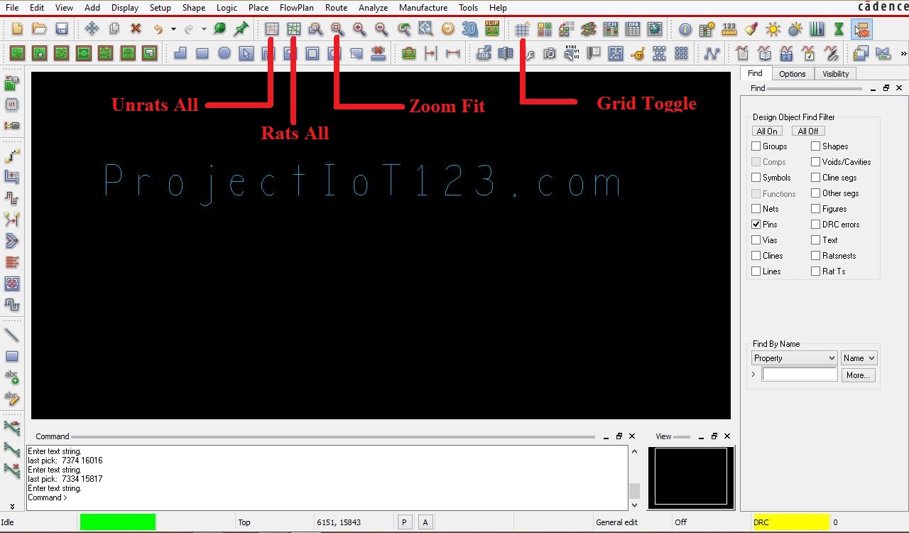
I will discuss in detail four basic commands that are “Grid Toggle”, “Zoom Fit”, “Rats All” and “Unrats All” as shown in the following image:
[otw_is sidebar=otw-sidebar-2]
Note:
Cadence Allegro Tutorials
| LIST OF Cadence AllegroTurorials | Names |
| Tutorial # 1 | Introduction to Allegro PCB Designer |
| Tutorial # 2 | Allegro Use “Add Connect Tool” |
| Tutorial # 3 | Allegro Use “Slide Tool” |
| Tutorial # 4 | Allegro Use “Hilight & Dehilight Tool” |
| Tutorial # 5 | Allegro Use “Show Measure & Grid” |
| Tutorial # 6 | Introcution to Nets in Allegro |
| Tutoiral # 7 | Introcution to Stackup in Allegro |
| Tutorial # 8 | Introcution to Copper Shapes in Allegro |
| Tutorial # 9 | Introduction Vias and GND Plane in Allegro |
ALL Orcad Allegro Tutorial for Beginner Ask free to Question us
What are Rats in Allegro PCB Designer?
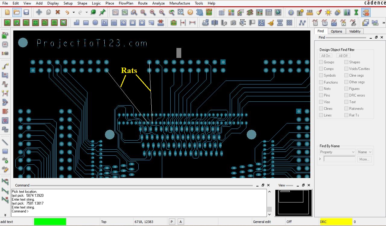
Before we continue let us know what are rats in Allegro PCB Designer? When the footprints of the components are placed in the outline of the board in Allegro PCB Designer and the routing is not started yet then the connection between the pins is shown by the straight line referred to as net as shown in the following image:
Now let us first discuss the “Grid Toggle” command.
Grid Toggle:
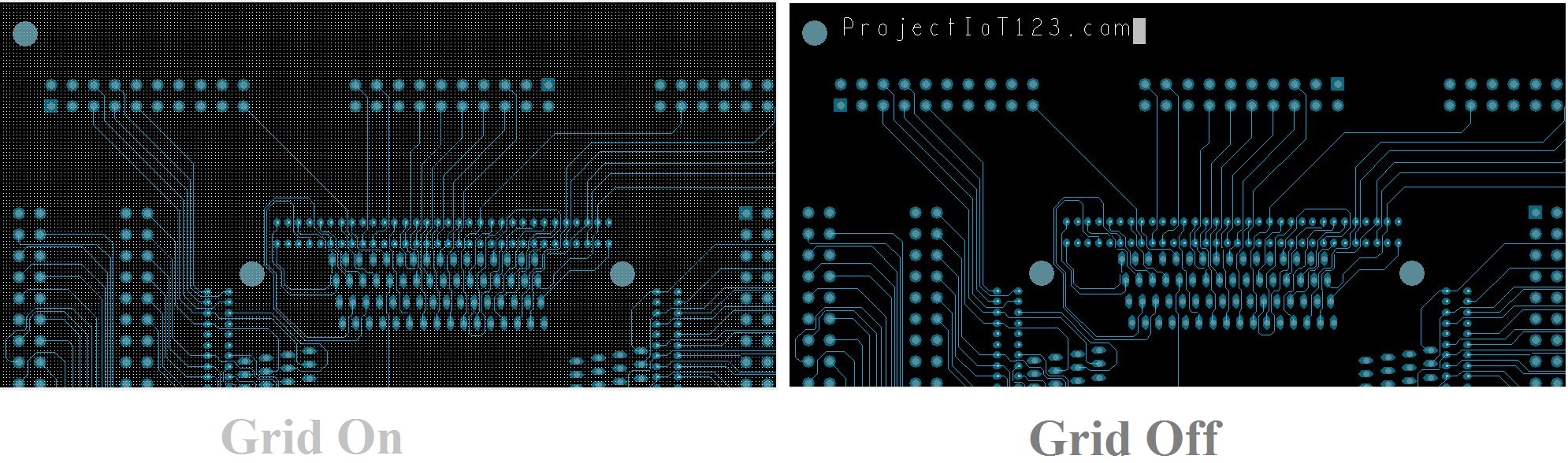
“Grid Toggle” command is used to turn the Grid on and off. Toggle means to either switch on or off the Grid. The grid is made on or off by left clicking on the “Grid Toggle” icon. When the Grid is turned on, it will be visible on the layout and when turned off it will not be visible but still remains there as shown in the following image:
The spacing between two points of the grid can be varies and it is sometimes quite useful, that is out of the scope of this tutorial but I will discuss it later.
Now let us consider “Zoom Fit”.
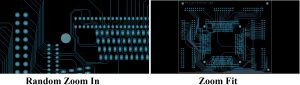
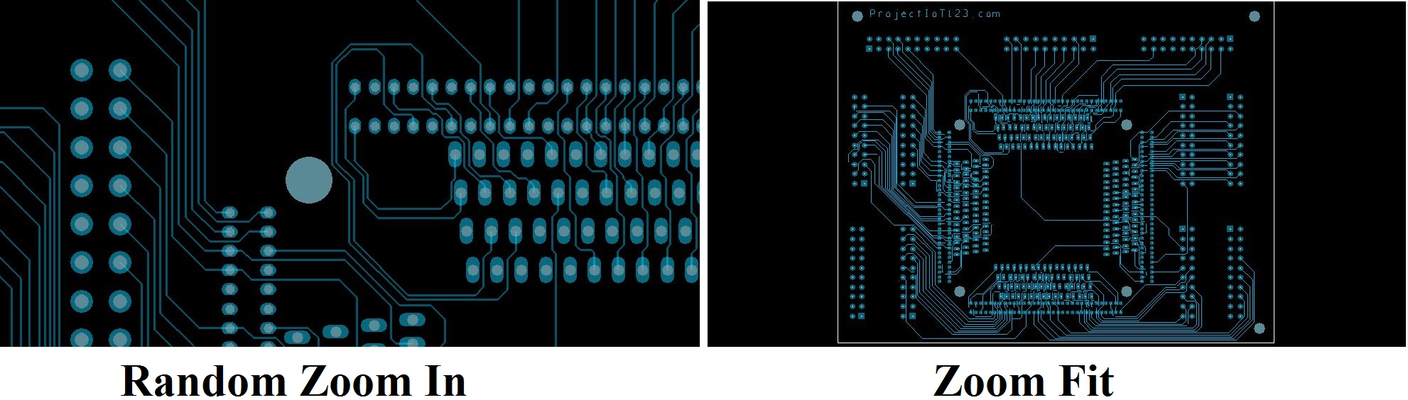
Zoom Fit:
“Zoom Fit” is another important command, while working on the board it is sometimes crucial to look at the overall layout in order to plan the route or place the component, so when the board is zoomed in then instead of continually pressing the zoom out command zoom fit is pressed once and board will fit into the window. “Zoom In” and “Zoom out” commands are not discussed as they are very simple. The following image shows the zoomed in board and when the “Zoom Fit” command is prompted:
 Rats All:
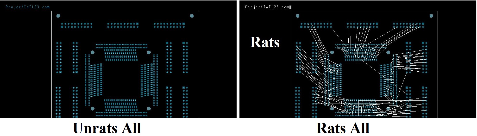
“Rats All” command is an important command that can be used to see whether any connection is left un-routed. As explained earlier that Rats are straight lines that shows the connections between the pins that are not routed yet. The following image shows the connection of the entire board that is not routed.
[otw_is sidebar=otw-sidebar-3]
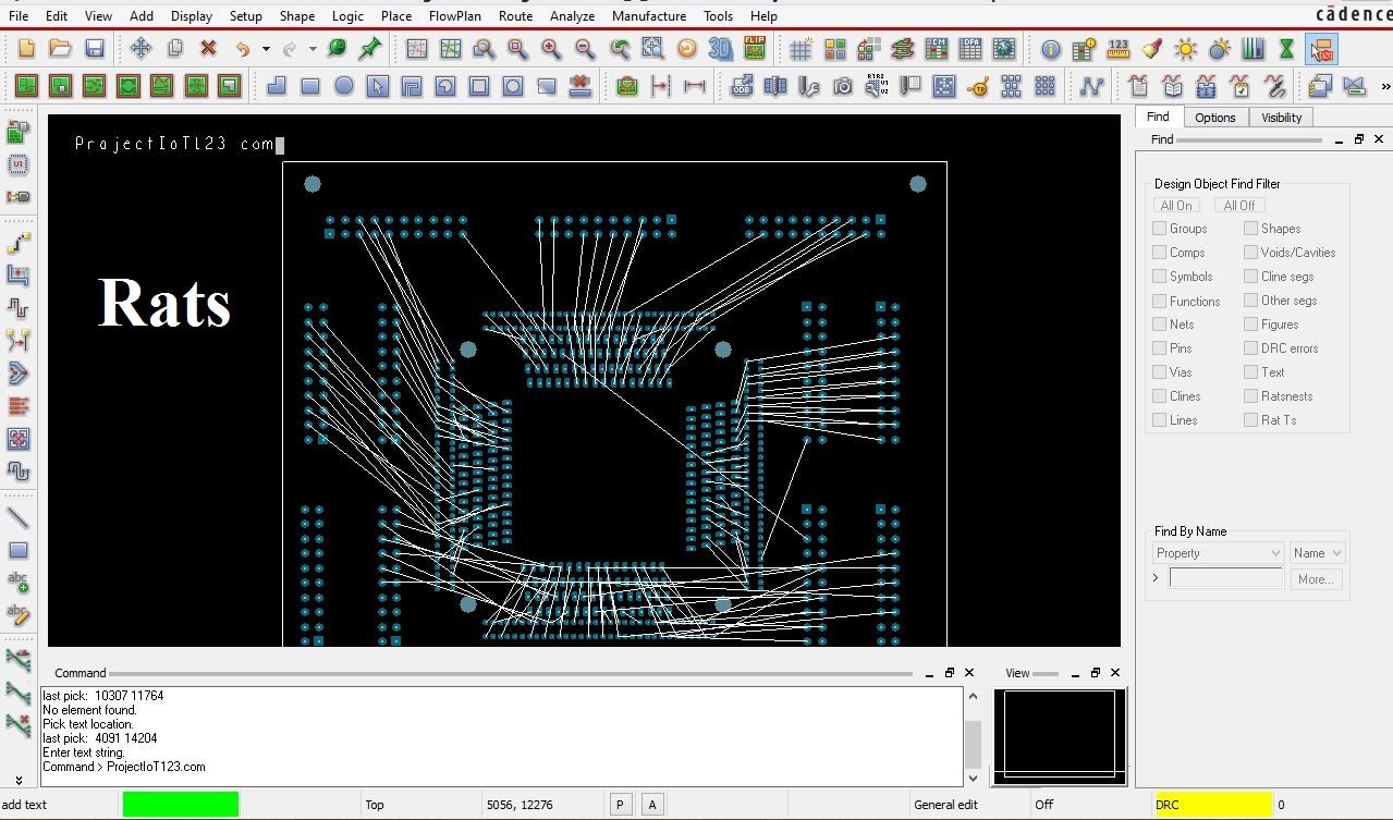
The “Rats All” command is used to display all the Rats thus one can see the pins that are not routed.
Unrats All:
“Unrats all” is counterpart of the “Rats All” as this command is used to disappear all the rats. While routing the board it is important to be organized so that the best route plan can be selected. When all the Rats are open (visible) the designer gets confused to search the route path so it is beneficial that all the Rats are turned off and only the Rats of those pins that are to be connected are turned on. So the “Unrats all” command is used turn off all the Rats. The method of turning the selected rats on will be discussed in the next tutorial. The following image shows the board when “Rats All” and “Unrats All” are pressed:
Introduction to Allegro PCB Designer (Part 6)
[otw_is sidebar=otw-sidebar-2]
That is all for now, I hope this tutorial would be helpful for you. In the next tutorial I will discuss about how to turn on the selected rats and other crucial techniques of routing. Till then stay connected, keep reading and enjoy learning.