

sg3525 inverter circuit diagram and sg3525 pinout Leave a comment
This article is all about sg3525 inverter circuit and sg3525 pinout
and its ic number. Keep reading if you want to know about inverter circuit using sg3525 ic
sg3525 inverter circuit diagram and sg3525 pinout
Components
c1=3nf
c2=1000uf
c3=100uf
c4=22nf
c5=3.3nf
c6=1uf
c7=2200uf
c8=10uf
R1=15k
R2=22
R3=1k
R4=470k
R5=2.2k
R6=10
R7=10
R8=1k
R9=1k
R10=56k
R11=1k
TRANSFORMER STEP UP 12 VOLTAGE TO 220 VOLTAGE
L1=5mh Coil
Diode 4007
Q1,Q2=IRF840
IC=3525
Battery 12v
sg3525 boost converter circuit
in this circuit i will show yoy how to 24 voltage to 400 voltage dc to dc step up .and how to circuit boost the voltage
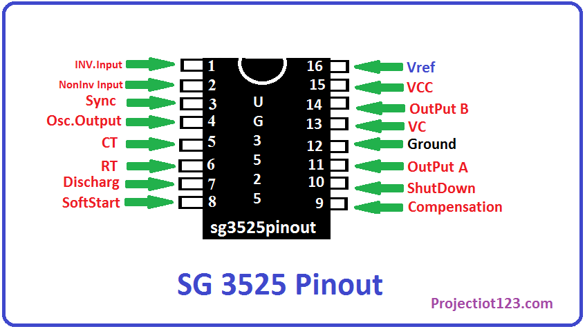
SG3525 pinout
sg3525 has 16 pins and it is pwm controller ic
sg3525 applications
- It is used for power supply circuit
- sg3525 is used for buck and boost circuit
- sg3525 is used for dc to dc chopper circuit
- battery charging circuit
- tv circuit
- inverter circuit