
lm35 temperature sensor working principle circuit diagram arduino code Leave a comment
[otw_is sidebar=otw-sidebar-1]Temperature Sensor Using Arduino
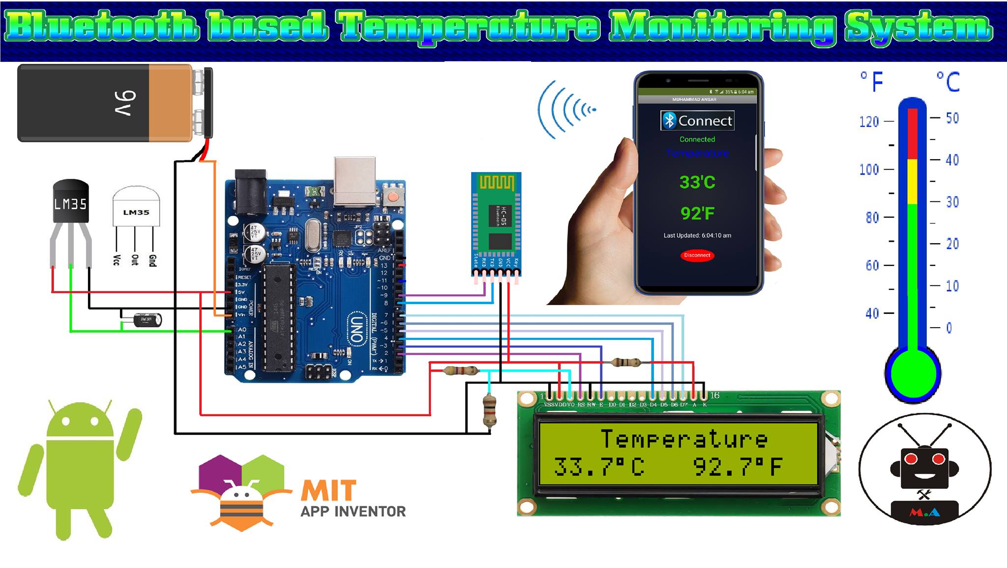
Hi friends! In this project, we will determine how to combine Temperature sensor with Arduino and applied a simple Arduino LM35 Temperature Sensor. To showing the output, I will attach the LM35 Temperature Sensor to Arduino and show the temperature readings on a LCD Module.
LM35 Temperature Sensor
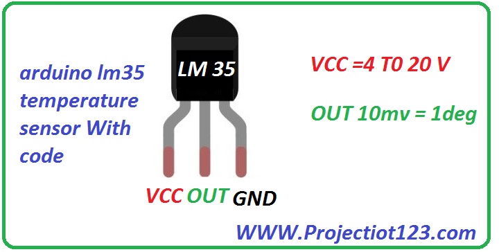
The LM35 is a well known Temperature Sensor. It is an accurate Temperature Sensor. It is also an analog sensor with its output voltage linear proportional to the temperature in C.
There are so many other devices in the LM series of temperature sensors like LM34 (measuring in Degree Fahrenheit) and LM335 (measuring in Kelvin) but LM35 seems to be very famous for DIY Projects.
lm35 pinout
 Comparing different LM35 sensors:
| LM Series | Temperature Range | Packages |
| LM35 | -55 to +150 C | TO-CAN |
| LM35A | -55 to +150 C | TO-CAN |
| LM35C | -40 to +110 C | TO-92 |
| LM35CA | -40 to +110 C | TO-92 |
| LM35D | 0 to +100 C | TO-92, TO-220 (Plastic) |
Arduino with Temperature Sensor
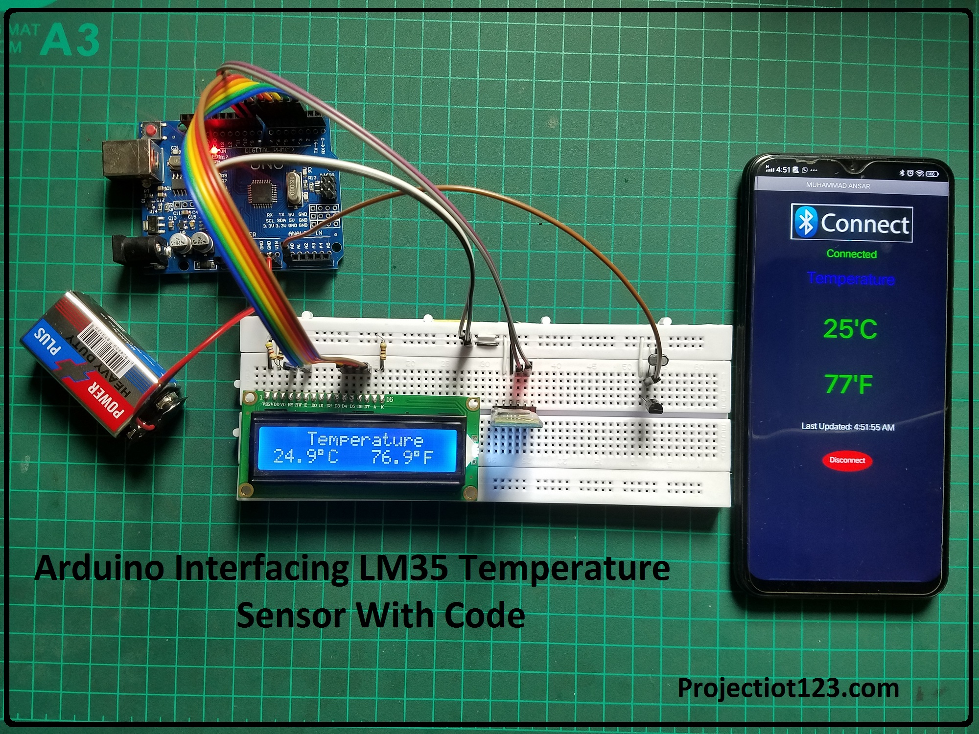
Although you can easily measure the temperature using LM35 Sensor and also a multimeter, a microcontroller like Arduino will be very helpful in showing the result on an LCD.
You can even make a web server using ESP8266 IC to show the temperature readings from the LM35 Temperature Sensor. But I will stick with Arduino and make a simple Arduino LM35 Temperature Sensor and show the result on a LCD.
#include <LiquidCrystal.h>

LiquidCrystal lcd(7, 6, 5, 4, 3, 2);
//          BS  E  D4 D5  D6 D7

float temp1,temp2,temp3;
float hum1,hum2,hum3;


int t11 =A0;
int l11 =A3;
int  GAS= A1;
int  HUM= A3;
int  flam= A2;

int fan =10;
int motor =11;
int spray =12;
int light =9;


char getData;

long tempReading ;
long tempReading1,tempc,t1 ;
long L1,G1,M1,H1,T1 ;

 char d1 = '0';
  char d2 = '0';
  char d3 = '0';
  char d4 = '0';


void setup()
{
  Serial.begin(9600);
lcd.begin(16, 2);


}

void loop()
{

delay(500);


   getad();

}

void getad(){ /// measure current and display on lcd
///////////////////////////////////////
//lcd.clear(); lcd.setCursor(0, 0);
tempReading1 = analogRead(t11);
   tempc = tempReading1 * 5000 / 1024;
t1=tempc;
lcd.setCursor(8, 1);  lcd.print("Temp=");
    d1=tempc/1000;
  d2=(tempc/100)%10;
  d3=(tempc/10)%10;
  d4=tempc%10;
   lcd.write(d1+48);
      lcd.write(d2+48);
   lcd.write(d3+48);
// lcd.print(".");
 //  lcd.write(d4+48);
}
Components Required
Arduino
LM35
Resistor
Virtual Teminal
Explaining Circuit:
The circuit diagram of the Arduino LM35 Temperature Sensor is easy. Analog pin A0 used as input of the Arduino. The output pin of LM35 is connected to Analog Input A0. Join LM35 output pin to it. Apply 5 volts to Vcc pin of LM35 and ground pin.
Working:
In this lesson, the LM35 senses the temperature and changes into an analog signal, and then this signal relates to Microelectronic through an analog-to-digital converter ADC. The analog signal is transform into digital format by the ADC. The value of temperature sensed by the sensor will be shows on Virtual Terminal.
Arduino LM35 Temperature Sensor Code
here is the simple circuit with mobile application
Application of LM35:
There are some applications of LM35 as follow
- It is very helpful for measuring the temperature of an environment.
- It gives thermal shutdown for a circuit.
- It can be utilized for battery temperature measurement. It also gives battery protection from overheating.
- It is mostly used in HVAC applications as a temperature measurement device.
So this is it. I hope you consider this guide useful. Let me know if you required any help with its projects. Will meets you guys next time. Till then take care, have more fun.
lm35 temperature sensor working principle circuit diagram arduino code