
Fast Line Follower Robot Using Arduino Leave a comment
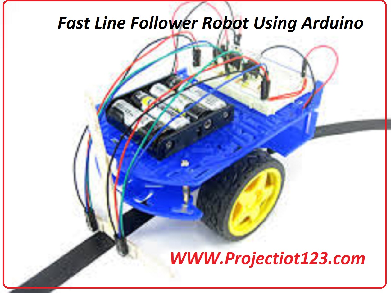
[otw_is sidebar=otw-sidebar-1] In this tutorial, I have built a Fast Line Follower Robot Using Arduino. In this lesson we will take a look at their components, working, and use of this project. So let’s begin.
Fast Line Follower Robot Using Arduino
A Line Follower Robot is an automated constructed vehicle, which follow a visual line implant on the floor. Normally, the specific line is the path in which the robot goes and it will be black line on a white floor. Determine the advanced Line Follower Robots use unseen magnetic field as their paths.
Large robots are normally utilizing in industries for helping the automated manufacturing process. They are also utilized in military applications, human support purpose, delivery services etc.
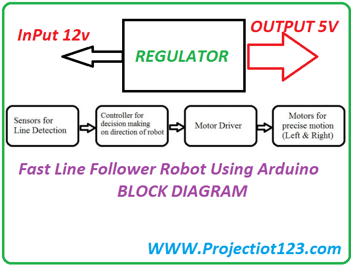
Block Diagram of Fast Line Follower Robot Using Arduino
Components Needed:
Arduino
L293D
LM016L
Motor DC
Potentiometer
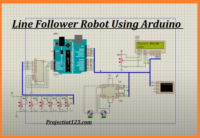
Circuit Diagram of Fast Line Follower Robot
Arduino is the main component of the project. It is a 15 pin Input and Output pins. This has many outermost features. The DC motors of the robot are attached to the controller using a motor driver. As the output of the controller is maximum 5v with very low current, it cannot drive the motors. So, to boost up the voltage motor driver is used. L293D can drive motors up to 36v and give a drive current of 3A.
The driver has 15 pins and is normally available in multiwatt15 Package. These ICs are available in the market as device. The inputs to the Motor Driver device are attached to PORT2 pins.
The two IR sensors are attached to pins of the Arduino. Prepare the chassis and connect the four wheels of the robotic vehicle to the motors that square measure successively connected to the Arduino.
 Working of Fast Line Follower Robot
The IR transmitter constantly transmits the IR rays. When IR transmitter is on the black surface these rays were suck up by the surface and when it is on white surface these rays were return. The IR receiver has most resistance once no IR rays square measure collect and voltage from Vcc meet up with the electrical device. At the output pin, voltage is 5v.
As the power of IR rays received by the receiver increases, resistance value decreases and reverse break down happen. The voltage of the resistor is grounded. So, at the output pin, it will generate 0v.
When the robot moves ahead, both the sensors wait for the line to be track. If the IR Sensor 1 in the image traces the black line, it means that there is a right curve forward.
Arduino trace this change and sends signal to motor driver correspondingly. In order to turn right, the motor on the right side of the robot is break down using PWM, while the motor on the left side is run at maximum speed.
Similarly, it is on left side forward then robot has to turn left. For the robot to turn left the motor on the left side of the robot is break down and the motor on the right side is run at maximum speed.
Arduino observing the data from both the sensors and command the robot to turn as the line traces by them.
int led = 13;
int out1 = 2;
int out2 = 3;
int out3 = 4;
int out4 = 5;

int b1 = A1;
int b2 = A0;
int b3 = 10;
int b4 = 11;

void setup() {
pinMode(led, OUTPUT); //set pin 13  as output
pinMode(out1, OUTPUT); //set pin   as output
pinMode(out2, OUTPUT); //set pin   as output
pinMode(out3, OUTPUT); //set pin  as output
pinMode(out4, OUTPUT); //set pin  3 as output
digitalWrite(out1, HIGH); // turn the LED on (HIGH is the voltage level)
digitalWrite(out2, HIGH); // turn the LED on (HIGH is the voltage level)
digitalWrite(out3, HIGH); // turn the LED on (HIGH is the voltage level)
digitalWrite(out4, HIGH); // turn the LED on (HIGH is the voltage level)
pinMode(b1, INPUT_PULLUP);
pinMode(b2, INPUT_PULLUP);
pinMode(b3, INPUT_PULLUP);
pinMode(b4, INPUT_PULLUP);

}

void loop() {
if(digitalRead(b2) == HIGH&&digitalRead(b2) == HIGH){
//fwr1();fwr2();
//delay(80);

}

if(digitalRead(b2) == HIGH){
fwr2();//delay(50);

}

if(digitalRead(b1) == HIGH){
fwr1();//delay(50);

}

if(digitalRead(b2) == LOW){
stop2();delay(5);}
if(digitalRead(b1) == LOW){
stop1();delay(5);}
}

void fwr1 (){
digitalWrite(out2, LOW); // turn the LED on (HIGH is the voltage level)
digitalWrite(out1, HIGH); // turn the LED on (HIGH is the voltage level)
}
void fwr2 (){
digitalWrite(out4, LOW); // turn the LED on (HIGH is the voltage level)
digitalWrite(out3, HIGH); // turn the LED on (HIGH is the voltage level)
}

void rev (){
digitalWrite(out1, HIGH); // turn the LED on (HIGH is the voltage level)
digitalWrite(out2, LOW); // turn the LED on (HIGH is the voltage level)

}

void stop1(){
digitalWrite(out1, HIGH); // turn the LED on (HIGH is the voltage level)
digitalWrite(out2, HIGH); // turn the LED on (HIGH is the voltage level)
}
void stop2(){
digitalWrite(out3, HIGH); // turn the LED on (HIGH is the voltage level)
digitalWrite(out4, HIGH); // turn the LED on (HIGH is the voltage level)
}
Applications of Fast Line Follower Robot
- Line follower Robots are normally used for automation process in industries, military applications.
- They are very helpful as they can work without any instructions i.e. they work as automatic manage vehicles.
- With additional features like hurdles avoidance and other security calculating, line follower robots are utilizing in driver less cars.
I hope this lesson gives you much information and I hope you enjoy this session. See you then in next lesson. Have fun