
full subtractor circuit diagram 4
Full Subtracrtor
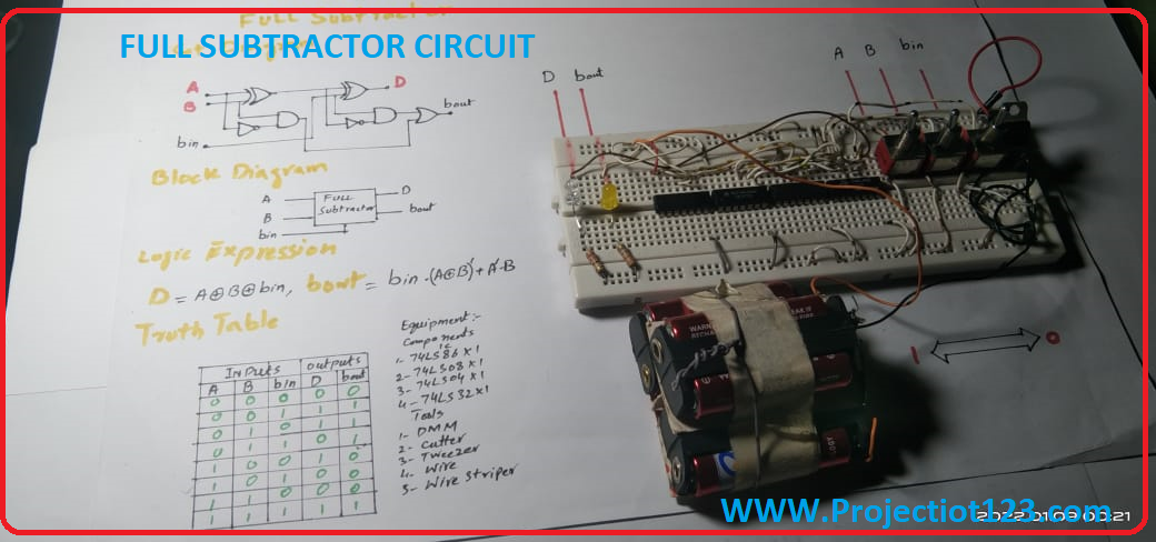
Today’s Tutorial(full subtractor circuit diagram) we are going to discuss combinational logic circuit named Full Subtractor . This circuit helps us in performing subtraction of 3binary inputs.
As you see in the block diagram Subsector have 2 input A & B and third one borrow in and 2 output Difference (D) and borrow out. The disadvantage of half subtractor is that it cannot cater the Borrow in.
As you see in the truth table 3 input mean 8 possible combination (0-7).
Now considering a combination from the truth.
A B Bin D Bout
1 0 1 0 0
For example B is subtracted from A, A-B=1, Bin is subtracted from A-B , 1-Bin=0, mean D is 0 and we does not take any borrow so the Bout is also 0.
After completing the procedure of subtraction between 3 bits (input variables) we get 2 outputs variable Difference (D) and Borrow out (Bout).
full subtractor circuit diagram
The output variables are simplified with K-maps & we make logic expression. After obtaining 2 output variables and their expression you need a circuit/ logic diagram. You can see the logic diagram in your screen. It consist 2 XOR, 2 AND, 2 NOT and 1OR GATES. TOTALL 7Nos gates are used in construction of Full Subtractor . Interesting thing is that it also consists of NOT gates.
Equipment:
Components
- 74Ls86 1Nos
- 74Ls08 1Nos
- 74Ls04 1Nos
- 74Ls32 1Nos
- Bread Board
- Toggle Switch 3Nos (for Input logic 0/1)
- LED 2Nos (for checking output status)
- Resister 470 Ohm 2 Nos
- 5volt DC Power supply
Tools
- DMM
- Side Cutter
- Tweezers
- Connecting Wires
- Wire Striper
Assemble the circuit as you see in your screen. At the end connect the Power supply.
Now we come to circuit testing process full subtractor circuit diagram
When all inputs (A,B, Bin) on Logic 0 than D and Bout is also on Logic 0.
If we set inputs A on logic 1 A=1,B on Logic 0 B=0 and Bin on Logic 1 Bin=1 with help of Toggle Switches.
we see the outputs D and Bout both outputs are on Logic 0 and no one LED is turn ON.
At the same way you can satisfy your truth table. So viewers following thesw designing step you can construct an operational Full subtractor.
Wow, amazing blog structure! How lengthy have you been running a blog for?
you made running a blog glance easy. The whole look of your
web site is fantastic, as well as the content material!
You can see similar here najlepszy sklep
Good day! Do you know if they make any plugins to assist with Search
Engine Optimization? I’m trying to get my website to rank for some
targeted keywords but I’m not seeing very good success. If you know
of any please share. Many thanks! You can read similar
article here: Backlinks List
Wow, awesome weblog structure! How lengthy have you been running a blog for?
you make running a blog look easy. The entire look of your web site
is wonderful, let alone the content! You can see
similar here dobry sklep
indian pharmacies safe https://indiaph24.store/# Online medicine order
mail order pharmacy india