IR2110 BUCK CONVERTER PROTEUS SIMULATION 1
Hello! Today’s topic is very interesting for you guys. It is about IR2110 BUCK CONVERTER. I will show you we use it in the Proteus. So let’s start the topic.
BUCK CONVERTER
“Buck converter is a popular DC-to-DC converter”.
[otw_is sidebar=otw-sidebar-1]
It is a step down converter. It converts a high voltage to a low voltage. The efficiency of a buck converter is higher than 90%. Buck converter has the ability to reduce heat and extend the battery life if the product. We can use it in a computer where it can’t heat up the system. The buck converter can be used in lots of cooling product.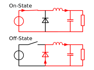
Working
 In this picture there are two modes. The one is ON and the other side is OFF. When the switch ON the supply voltage will flow current from this loop and the partial current will flow from this capacitor and inductor will charge by Polarity.
On the other hand when the switch off the charge energy in the inductor that inductor will reverse its polarity. After this the inductor will release its energy thought the load. Now the current will flow from resistor, then capacitor and then diode.
In short we can say that when switch is ON the inductor will store its energy with positive polarity. When the switch is OFF the inductor will release its energy by changing its polarity.
Let start the project on Protues
BUCK CONVERTER SIMULATION in PROTEUS Using IR2110
 For making this circuit we have to use following components.
- Resistor
- Diode
- Capacitor
- Inductor
- IR2101
- MOSFET Driver
Resistor
A resistor is a substance which opposes the flow of electron through it. The SI unit of resistor is ohm. It is represent by R . The formula is V=IR. V potential, I current and R resistance.
Diode
A diode is a device in which the current is flow only in one direction. The current is flowing from anode to cathode. As you see in the picture. The SI unit of diode is Volt.
Capacitor
A capacitor is act as a battery. It can store energy in it. The energy is in the form of electrical charges. The SI unit of capacitor is Farad.
Q=CV
Inductor
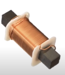
An inductor is also called a coil. It is an electrical component that stores energy in a form of magnetic field when electric current pass through it. The SI unit of inductor is Henry (H). di/dt=0
IR2101
The IR2101 are high voltage. MOSFET drivers with high and low side output. The maximum off set volt is up to 600V. The gate supply range from 10 to 20V. The logic input is from 3.3v.
Vcc =Low side and logic fixed supply voltage
Vs= High side floating supply offset voltage
Hin= High side gate driver output
HO= High side gate drive output
Lin= Low side gate driver output
LO = Low side gate drive output
COM= Low side return
MOSFET Driver:
The MOSFET (metal oxide semiconductor field effect transistor) is a transistor which used for switching electronic signals. MOSFETs are having high switching up to 100 khz. The controller current is dependent on the base current hence the current is highly dependent on the junction temperature. MOSFETs are comprised of n channel and p channel but they are arranged in different style
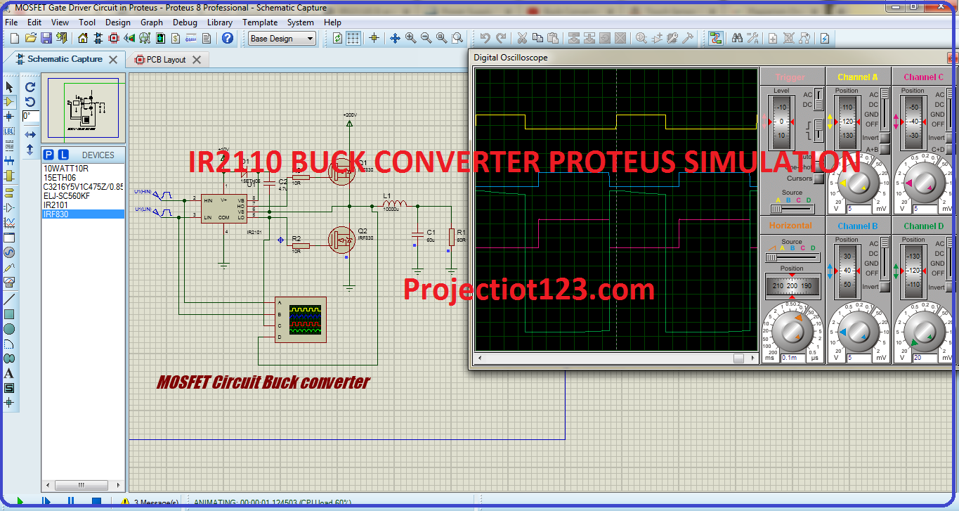
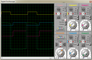 I will tell you about the waveform which is display on the oscilloscope. So the first yellow shows the high side logic signal. Second blue wave shows the low side logic signal. Third pink wave shows the output of the low side and then the fourth drain signal of the low side MOSFET. As you can see that by using buck converter we can easily shows our signal in the form of wave by using oscilloscope.
In this article, I showed you how to use IR2101 as inverter and also performed the project: Buck Converter
Hope you enjoyed this project & stay connected for upcoming new topics.




Online medicine home delivery https://indiaph24.store/# buy medicines online in india
cheapest online pharmacy india