
Introduction to RL Circuit 1
[otw_is sidebar=otw-sidebar-1]This is the twelfth article”Introduction to RL Circuit” in the series on the introduction to basic electronic components. In the previous article I have discussed the RC circuit, its working, operation and applications in this article I will discuss the RL circuit.
After reading this post the reader will be able to learn about the operation of the RL circuit and its applications. So sit back, keep reading and enjoy learning.
Introduction to RL Circuit:
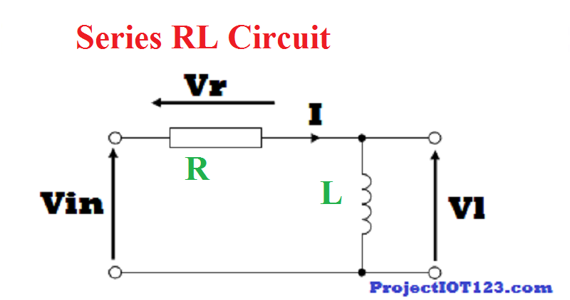
The RL circuit is the combination of the two basic electrical components that is resistor and capacitor. Resistor and capacitor can either be connected in parallel or in series and as they can be described by the first order differential equation that is why they are called first order circuits. Like the RC circuit the LR circuit can also be used as the filter but capacitor is more commonly used with the resistor for filter applications as they can be easily manufactured and are smaller in size. The RL circuit can be employed as the low pass filter or the high pass filter depending upon the element from which the output is derived. The series RL circuit is as shown in the following figure:
[otw_is sidebar=otw-sidebar-2]
Operation of the RL Circuit:
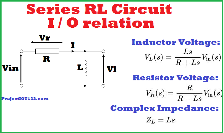
The series combination of the resistor and inductor is used as the filter to pass certain frequencies and block the others. This behavior is due to the frequency dependent complex impedance of the inductor. As we all know that the inductor acts as the short circuit for the Dc current that is it allows the DC current to pass without resistance and opposes the flow of alternating current due to the self-inductance. When the output is taken from the inductor as shown in the above image then the RL circuit behaves as the high pass filter as the inductor will filter all the low frequencies signal content due to low complex impedance. On the other hand when the output is taken from the resistor then it low pass filter and block the high frequency signal content. The input-output relation for both configurations is shown below and the complex impedance is also shown. The behavior can be understood more easily using the equation.
What is RL Circuit
The inductor voltage equation and the resistor voltage relate the input and output in s-domain that is in the complex frequency domain. As seen in the complex impedance of the inductor that as the frequency of the input signal increases the complex impedance of the inductor increases and now note in the inductor voltage equation that as the complex impedance reduces the with the decreases in the input signal frequency then the voltage drop across the inductor also reduces and it will eventually become zero for zero frequency signal. Thus in this way the RL circuit acts as the high pass filter when the voltage is taken from the inductor. Similar is the case for the low pass filter.
HERE is RL Circuit Differential Equation
[otw_is sidebar=otw-sidebar-3]
Applications of the RL Circuit:
Most common applications of the RL Circuit is in passive filter designing. Some of the applications of the RL combination are listed in the following:
- RL circuit is used as passive low pass filter.
- RL circuit is used as passive high pass filter.
- RL circuit is used in feedback network of op amp.
- RL circuit is also used in power supplies.
- RL circuit is also employed in RF equipment.
I hope this article”Introduction to RL Circuit” would be helpful for you. I have discussed basic operation of the RL circuit in this article. That is all for now in the next article I will come up with more interesting engineering topics. Till then stay connected, keep reading and enjoy learning.
cipro: ciprofloxacin mail online – cipro 500mg best prices