
Raspberry PI GPIO interface with A4988 5
[otw_is sidebar=otw-sidebar-1]In this post I will discuss about how to interface the Raspberry Pi with the A4988 motor controller. In the previous posts I have discussed how to interface the Raspberry Pi with the Servo Motor and Stepper motor. The raspberry Pi was controlling the Stepper motor using the L298 motor controller. There are a number of other motor controllers each optimized for a special function. This post will be oriented around interfacing the Raspberry Pi with the A4988 motor controller to control the Bipolar Stepper motors.
[otw_is sidebar=otw-sidebar-2]
Raspberry PI GPIO interface with A4988
After reading this post you will learn about A4988 motor controller, its pin configuration, circuit for the A4988 motor controller and how to control the stepper motor using Raspberry Pi in Python language.
Equipment Required:
For the sake of this post you will need the following equipment:
- Raspberry PI.
- A4988 motor controller.
- Breadboard.
- Jumper wires.
- Stepper motor
- Power supply.
A4988 motor controller:
[otw_is sidebar=otw-sidebar-3]
The A4988 motor controller is the micro-stepping driver for controlling the Bipolar Stepper motor. The controlling scheme of the A4988 motor controller for stepper motor is quite simple as compared to the L298N motor driver as it utilizes only two pins for controlling the stepper motor, one pin control the steps of the Stepper Motor and the other pin control the direction of the Stepper Motor. We will go into details of the pin description of the A4988 motor driver in the next section. This Stepper motor driver can operate in five different modes:
- Full-step.
- Haft-step.
- Quarter-step.
- Eight-step.
- Sixteen-step.
The other benefit of this motor controller over the L298N is the over-temperature protection and over current protection, in addition the output current of the driver can also be controlled via potentiometer. The A4988 motor driver comes in the modular form with translator and over current protection as shown in the following image and it is based on the A4988 driver IC shown in the same image.
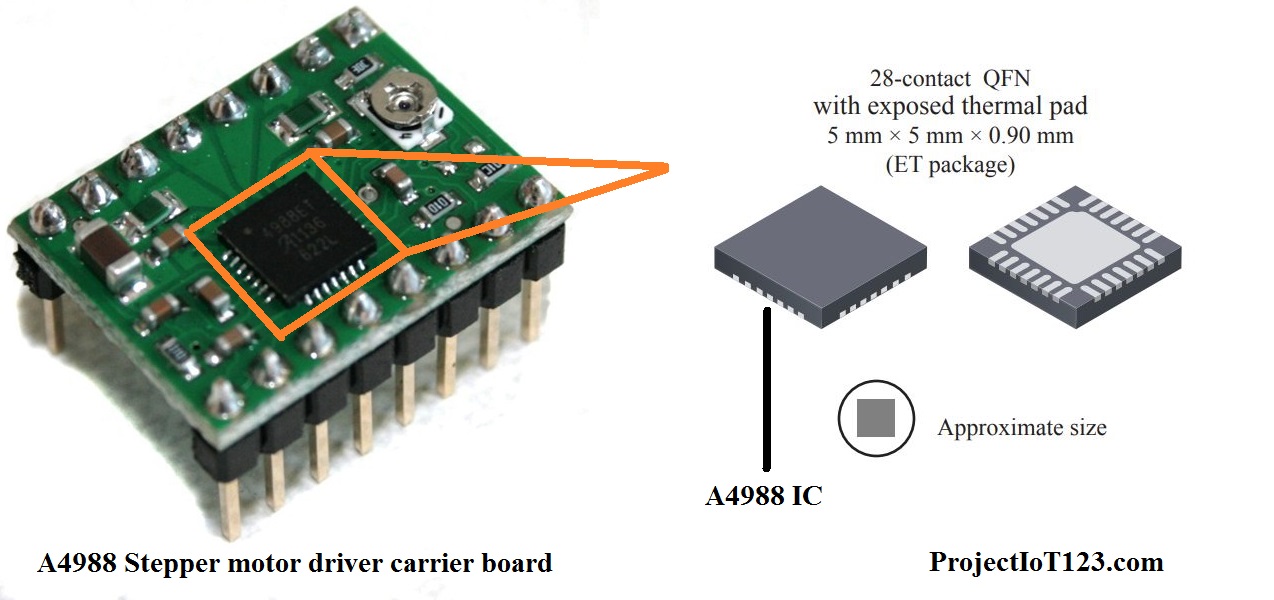
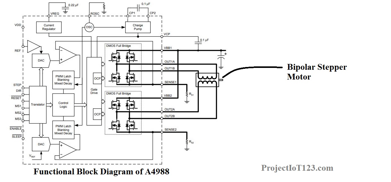
The A4988 motor driver is capable of providing 2 ampere current at the output and can drive one bipolar stepper at a time. The functional block diagram of the A4988 motor driver is as follows:
Here in this post we will only consider the A4988 carrier board and will discuss everything in reference to the board.
Pin description of the A4988:
As described in the previous section that the A4988 motor driver is capable of controlling only single Bipolar Stepper Motor that it has four pins dedicated to drive the Bipolar Stepper Motor, two of the four pins control one winding of the Stepper motor and the other two pins control the other winding of the Bipolar Stepper Motor. In addition there are two pins dedicated to control the movement of the Bipolar Stepper Motor. One pin that is the step pin controls the steps of the stepper motor and the other pin dir pin controls the direction of the stepper motor. The pinout of the A4988 stepper motor driver is shown in the following image.

The basic circuit configuration of the A4988 motor driver is shown in the following image:
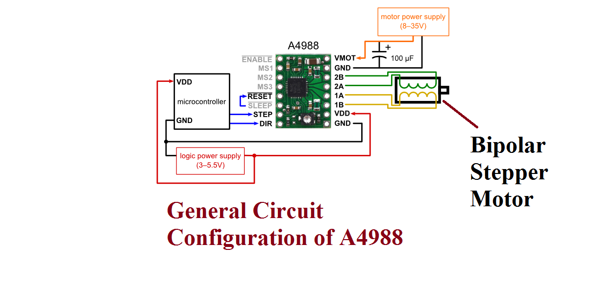
Notice in the figure that the Stepper motor controller utilizes two power supplies one is for the logic of the driver and the other (8-35V) is for providing the driving current to the stepper motor. Here we will be using the Raspberry Pi as the controller.
Raspberry Pi A4988 Stepper Motor Driver:
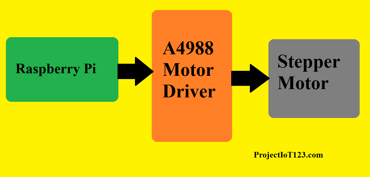
As would be clear in the above sections that the stepper motor driver we are using for the sake of this post can drive one stepper motor at a time and has two controlling pins to control the stepper motor one is for the Stepping of the stepper motor and the other is for the direction. Two power supplies are utilized for driving the stepper motor. The General Purpose Input / Output pins of the Raspberry Pi are connected to the A4988 motor driver control pins that is one of the GPIO pins of the Raspberry Pi is connected to the step pin and one to the dir pin. The GPIO pins will command the A4988 motor driver to control the steps and direction of the Stepper Motor. The Block diagram of the Raspberry PI and the stepper motor driving system is as shown in the following image:
Circuit Diagram:
[otw_is sidebar=otw-sidebar-3]
The circuit diagram for the Raspberry Pi controlling the Bipolar Stepper Motor using the A4988 motor driver carrier board is shown in the following figure:
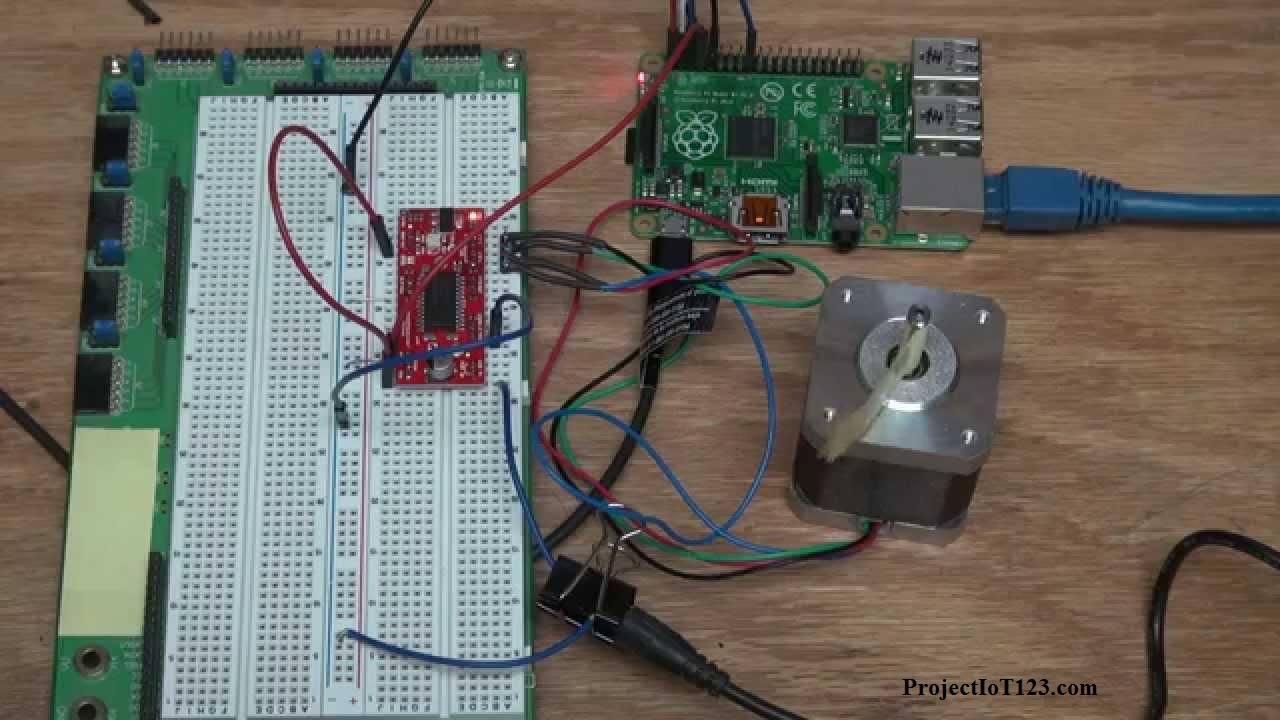
The GPIO pins number 18 of the Raspberry Pi is connected to the step pin of the Stepper Motor Driver and the GPIO pin number 19 is connected to the dir pin of the Stepper Motor Driver. Each pulse through the Raspberry Pi pin creates one step for the Stepper Motor.
That is all for now I hope this article would be helpful for you in the next post I will come up with more interesting applications of the Raspberry Pi till then stay connected, keep reading and enjoy learning.
[otw_is sidebar=otw-sidebar-3]
In this post “Raspberry PI GPIO interface with A4988“I will discuss about how to interface the Raspberry Pi with the A4988 motor controller. how to interface the Raspberry Pi with Stepper motor.
raspberry pi gpio programming example for servo motor Using Python
Raspberry Pi GPIO PINS with Stepper Motor using L298 Motor Controller
how to control motor with raspberry pi using l298 and send me code of Raspberry Pi 3
Where is the Python code in this story, would like to see it to test it.
Raspberry PI GPIO interface with A4988
Thanks!
Hi-
Can you also point me in the direction of the Python code?
Thanks!
Hi, all the time i used to check webpage posts here in the early hours in the
daylight, as i love to find out more and more.
Feel free to visit my blog post :: vpn special
At this time it seems like Movable Type is the best blogging platform available right now.
(from what I’ve read) Is that what you’re using on your blog?
my web page – vpn special code