
Programmable timer using 8051 with code in proteus
Programmable timer using 8051 with code in proteus
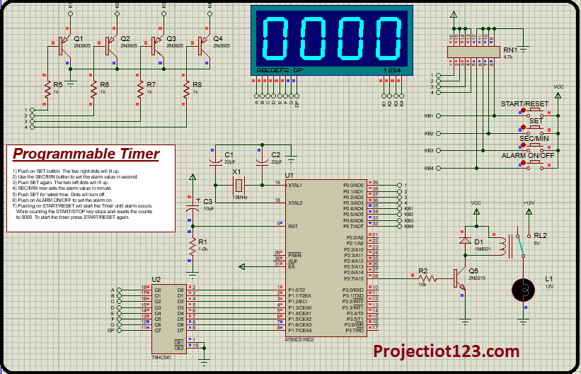
In this article we will learn how to make Programmable timer using 8051 with code in proteus.
In the last post we will learn how to Interface 8051 with external memory in proteus. You can visit our website,
I hope you appreciate my work, let’s discuss about today’s project.
Components:
- IC (8051)
- IC (74HC541)
- Display (7 segment 4digit Blue)
- Transistors
- Resistors (1k, 10k)
- Resistor Network Array (4.7K)
- Push buttons
- 5V Relay
- Diod (4007)
- Lamp (12V)
- Capacitors (22pF, 10uF,)
- Crystal (1.2MHz)
- Jumper wires
Construction…
- Connect pin 18 of 8051 with one side of capacitor 33p through the one side of crystal
- Connect 2nd side of capacitor with one side of 2nd capacitor and then connect them with GND
- Connect the pin 19 of 8051 with 2nd side of crystal through the 2nd side of 2nd capacitor
- Connect one side of resistor 1k with GND
- Connect 2nd side of resistor with one side of capacitor 10uF
- Connect 2nd side of Capacitor 10uF with +ve
- Connect pin 9 of 8051 at the junction of resistor and capacitor
- Connect pin 1 of 8051 with pin 2 of 74HC IC
- Connect pin 2 of 8051 with pin 3 of 74HC IC
- Connect pin 3 of 8051 with pin 4 of 74HC IC
- Connect pin 4 of 8051 with pin 5 of 74HC IC
- Connect pin 5 of 8051 with pin 6 of 74HC IC
- Connect pin 6 of 8051 with pin 7 of 74HC IC
- Connect pin 7 of 8051 with pin 8 of 74HC IC
- Connect pin 8 of 8051 with pin 9 of 74HC IC
- Connect pin 1 & 9 of 74HC IC with GND
- Connect pin 11 of 74HC IC with DP pin of 7 Segment display
- Connect pin 12 of 74HC IC with G pin of 7 Segment display
- Connect pin 13 of 74HC IC with F pin of 7 Segment display
- Connect pin 14 of 74HC IC with E pin of 7 Segment display
- Connect pin 15 of 74HC IC with D pin of 7 Segment display
- Connect pin 16 of 74HC IC with C pin of 7 Segment display
- Connect pin 17 of 74HC IC with B pin of 7 Segment display
- Connect pin 18 of 74HC IC with A pin of 7 Segment display
- Connect pin 28 of 8051 with one side of Resistor 10K
- Connect 2nd side of Resistor 10k with signal pin of transistor
- Connect ammeter pin of transistor with GND
- Connect collector pin of transistor with one side of diod through one terminal of 5V relay
- Connect 2nd side of Diod and 5V relay with VCC
- Connect 3rd terminal of 5V relay with +12V
- Connect 4th terminal of 5V relay with one side of 12V Lamp
- Connect 2nd side of Lamp with GND
- Connect K1 pin of 7segment display with collector pin of 1st transistor
- Connect ammeter pin of 1st transistor with GND
- Connect signal pin of 1st transistor with one side of resistor 1k
- Connect 2nd side of 1k resistor with pin 1 of RN1
- Connect K2 pin of 7segment display with collector pin of 2nd transistor
- Connect ammeter pin of 2nd transistor with GND
- Connect signal pin of 2nd transistor with one side of resistor 1k
- Connect 2nd side of 1k resistor with pin 2 of RN1
- Connect K3 pin of 7segment display with collector pin of 3rd transistor
- Connect ammeter pin of 3rd transistor with GND
- Connect signal pin of 3rd transistor with one side of resistor 1k
- Connect 2nd side of 1k resistor with pin 3 of RN1
- Connect K4 pin of 7segment display with collector pin of 4th transistor
- Connect ammeter pin of 4th transistor with GND
- Connect signal pin of 4th transistor with one side of resistor 1k
- Connect 2nd side of 1k resistor with pin 1 of RN1
- Connect pin 13, 14, 15, 16 of RN1 with +ve
- Connect pin 9, 10, 11, 12 of RN1 with GND
Working…
A programmable timer using the 8051 microcontroller typically involves configuring one of the 8051’s built-in timer counters to perform various timing and counting functions. The 8051 microcontroller is a popular microcontroller that includes multiple timer counters, often labeled as (T0) Timer 0 and (T1) Timer 1. These timer counters can be programmed to generate precise time delays, count external events, and control various timing-related operations in embedded systems.
Applications…
- Industrial Automation
- Traffic Light Control
- Home Automation
- Ultrasonic Distance Measurement
- Security Systems
Advantages…
- Precision Timing
- Real-Time Applications
- Energy Efficiency
- Ease of Programming
- Cost-Effective Solution
Program code…