
Arduino and LCD simulation in Proteus 20
[otw_is sidebar=otw-sidebar-1]In this article I will discuss about the simulation of the Arduino and LCD in Proteus. In the previous article I have discussed the installation of Arduino Library in the Proteus. So this article will be oriented around the Arduino and LCD simulation and you only need to download the LCD library for Proteus which is quite simple. So sit back, keep reading and enjoy learning.
[otw_is sidebar=otw-sidebar-2]
The LCD and Arduino interfacing is quite common in several projects. It is very important to check the code of Arduino before physical implementation as there are number of pins included in the Prototype. So Arduino code for LCD should be simulated first to avoid any error in the circuit and assembling and disassembling the circuit again and again. To simulate the Arduino UNO and LCD circuit in the Proteus libraries for both Arduino and LCD must be installed in the Proteus. I have already discussed the installation of the Arduino Library in the Proteus. In this article you will learn how to download the LCD library for Proteus and install it in the Proteus and simulate the circuit in the Proteus. Follow the following simple steps.
Step 1 Download LCD Library for Proteus
First of all download the LCD library for Proteus. Simply search for the LCD library in your web browser and look for the library. Simply download the Library, unzip it and copy paste it in the Proteus as we did in the case when installing the Arduino library. This step is very simple. Please see the previous article if you face any problem. It must be noted Proteus 8.0 has already installed LCD library so you do not need to download the LCD library. Simply search for the LCD and add it in the workspace. Assemble the circuit shown in the following image:
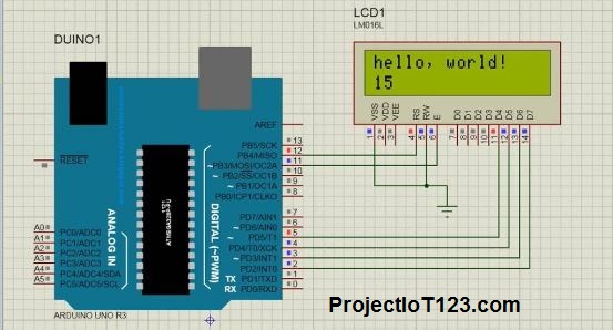
As you can see in the Picture above the LCD has eight data pins, Rs pin, Rw pin which has been grounded, Vdd and enable pin. The LCD can be used in two modes, eight pin mode and four pin mode. I will be using the four pin mode that is I will use four digital data pins to communicate to the Arduino. As you can see in the image above Enable pin and Register select pin are left open. These pins are intended to be connected to the Arduino Digital pin. The four data pins are connected to the Arduino digital pin too. Vdd pin is connected to voltage source and Rw pin and Vee pin is grounded.
Step 2:
After you have assembled the basic circuit for the LCD it’s time to add Arduino in the workspace and make connections of LCD with the Arduino. The Arduino is interfaced with the LCD like the shown in the following picture.
[/vc_column_text][/vc_column][/vc_row][vc_row][vc_column][vc_btn title=”download this file” style=”classic” color=”green” link=”url:http%3A%2F%2Fprojectiot123.com%2F2019%2F03%2F10%2Fultrasonic-sensor-library-in-proteus%2F|title:flex%20sensor%20library%20for%20proteus|target:%20_blank|”][/vc_column][/vc_row]
The data pins of the LCD are connected to the Digital I/O pins of the Arduino according to the program. In other words those digital input/output pins which are used in the code of the Arduino interfacing with LCD are connected with the data pins of the LCD. The enable pin and the Rs pins are connected to the Arduino digital I/O pins too.
[otw_is sidebar=otw-sidebar-3]
Step 3:
Once you have made the all the required connections it’s time to write the code. So open the Arduino IDE and write the code for LCD. You can also copy the code I have written which is shown below.
const int rs = 12,
const int en = 11,
const int d4 = 5,
const int d5 = 4,
const int d6 = 3,
const int d7 = 2;
LiquidCrystal lcd(rs, en, d4, d5, d6, d7);
void setup() {
// set up the LCD's number of columns and rows:
lcd.begin(16, 2);
// Print a message to the LCD.
lcd.print("hello, world! 15");
}
void loop() {
// set the cursor to column 0, line 1
// (note: line 1 is the second row, since counting begins with 0):
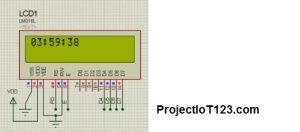
lcd.setCursor(0, 1);
// print the number of seconds since reset:
lcd.print(millis() / 1000);
}
Step 4 lcd 16×2 proteus library and hex file:
Now you need the HEX file for the code you have written in the Arduino IDE. This HEX file will be uploaded in the Proteus which will be ready for simulation. I have already discussed the about how to create HEX. I am repeating it
Open your Arduino IDE, click on the File, go into preferences and check the boxes with compilation and uploading.
When you have check the boxes highlighted in the above write the code and then compile.
Once you have compiled the code by clicking the Verify button at the top left corner of the Arduino IDE. The Arduino IDE will automatically create the HEX file and give the link of it at the bottom.
Go to the link as specified by your Arduino IDE and you can find your HEX file there.
[otw_is sidebar=otw-sidebar-2]
Step 5:
After you have made the HEX file it should be in some way given to the Proteus so that Proteus can use this HEX file to simulate the code and thus simulate the circuit. I am discussing here the steps for setting the HEX file in Proteus.
Open you Proteus.
Browse for the HEX file in the location where your newly created hex file is placed.
Finally click on the file and the hex file will be uploaded in the Proteus.
Now the Proteus is ready for simulating the Arduino circuit.
This is all about today’s article. I hope it would be helpful for you.
[otw_is sidebar=otw-sidebar-3]