

Introduction to OR Gate 577
[otw_is sidebar=otw-sidebar-1][otw_is sidebar=otw-sidebar-2]
Hello friends, I hope you all are fine and good health. Today I discuss with you about Introduction to OR Gate. In previous post I discuss about Introduction to NOT Gate all the friends likes that post and good comments so I impressive from our friends and today I have new post share with you about Logic Gates
Introduction to OR Gate
Digital logic gates are the building blocks of the digital circuit. Each basic logic gate implements a unique Boolean function and a complex Boolean expression is implemented using the network of basic gates. Three basic logic gates are:
These basic digital logic gates can be connected in peculiar ways to form other important logic gates. Logic gates formed by the peculiar combination AND, OR and NOT are:
OR Gate implements the OR Boolean function and similarly AND and NOR Gates implements the OR and NOR functions respectively. Here the discussion will be oriented around the OR Gate only.
OR Gate:
OR Gate is one of the basic logic gates that implement the logical OR operation. The Boolean expression that represents the logical conjunction and thus represents the functionality of the OR Gate is as shown below:
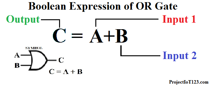 As shown OR Gate function is represented by the plus sign. OR Gate operates on minimum two inputs and depending upon the state of each input it delivers the output which is governed by the Boolean OR function. In Boolean algebra each variable can have one of the two values that is ‘0’ or ‘1’. Thus in the Boolean expression of the OR Gate the inputs A and B can assume either ‘0’ or ‘1’ and C which is the output of the OR function of input A and input B also assumes either ‘0’ or ‘1’.
Truth Table of OR Gate:
The relation between the state of the output and that of the inputs is represented in the form of the table. This table is called the Truth Table. The Truth Table of the OR Gate along with its schematics symbol is shown below:
In order for the output to be HIGH one of the inputs A or B should be HIGH, the output is also HIGH when both A and B are HIGH otherwise the output would be LOW as represented by the truth table. In terms of Positive Logic ‘1’ is considered to be ‘HIGH’ and ‘0’ is considered as ‘LOW’ and in terms of Negative Logic ‘1’ is considered as ‘LOW’ and ‘0’ is considered to be ‘HIGH’.
OR Gate Circuit:
Now let us understand the circuit that implements the OR Gate. OR Gate can be implemented in a variety of ways depending upon the electronic components used to design the circuit. For example diodes, transistors, resistors and combination of these components can implement the OR Gate. The most popular techniques for designing the OR gates are TTL (Transistor-Transistor Logic) and CMOS (Complementary Metal Oxide Semiconductor Transistor) logics. An example of the circuit implementing the OR Gate is shown in the figure below:
[otw_is sidebar=otw-sidebar-3]
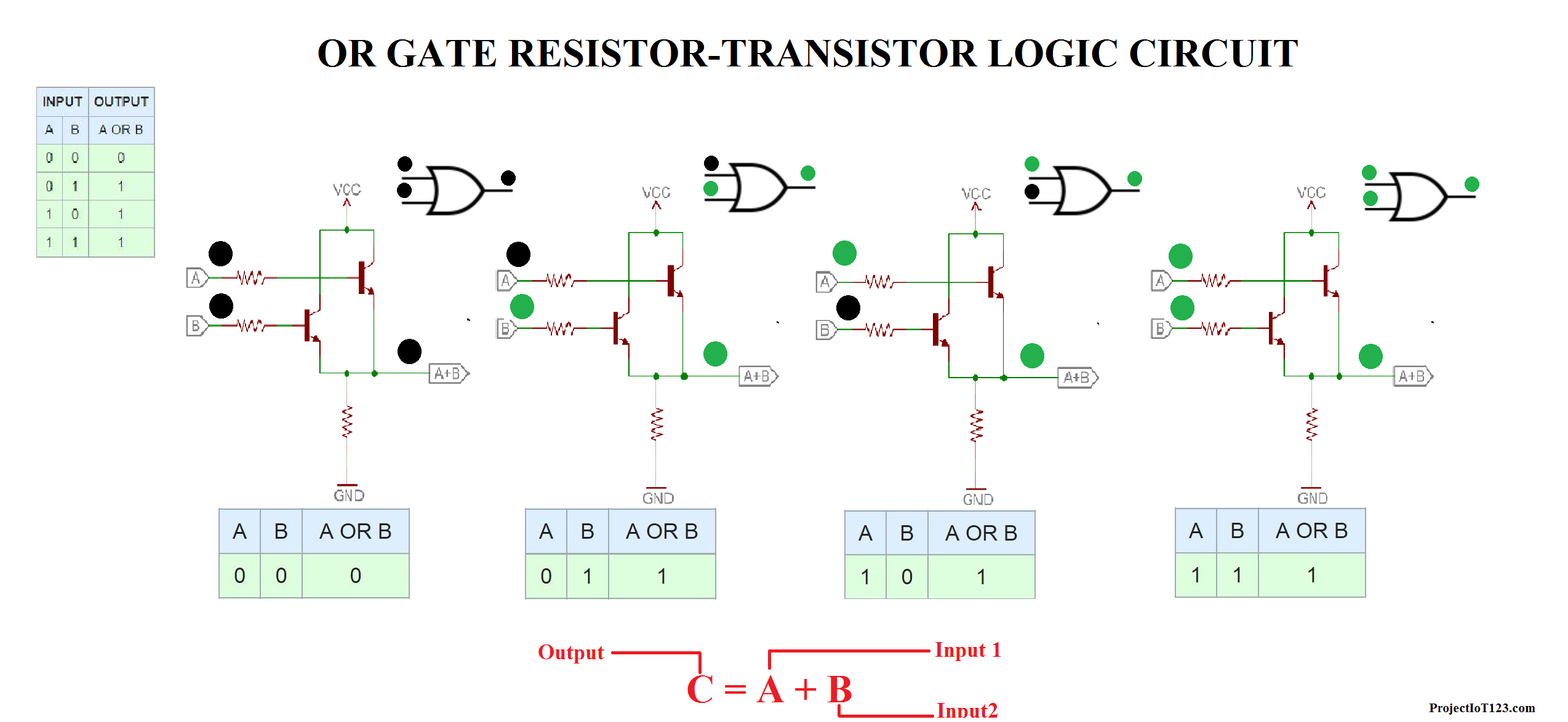 The inputs of the OR Gate are connected to base of the transistors and the output is connected to the emitter. As shown in the figure when either of the inputs A and B is HIGH the output is also HIGH or if one of the inputs is HIGH the output is HIGH as well. Here transistor acts as the switch when both or one of the transistors are on the voltage will appear at the emitter. It is important to note here that 5V represents the logic HIGH and 0 V represents the logic LOW.
OR Gate IC 4071:
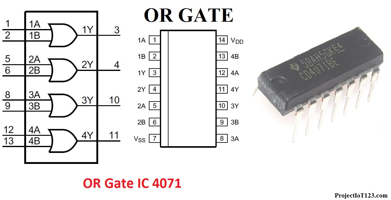
OR gates are available in the IC packages. One of the most popular IC for OR Gate is 4071 which is a Quad-two input OR Gate IC which means that this IC contains 4 independent two input OR Gates. The pinout and connection diagram of the 4071 IC is shown below:
OR Gate Symbol:
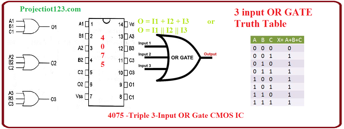
OR Gate cmos 3 input or gate truth table :
OR gates are also available in the cmos IC packages. As mentioned earlier that CMOS (Complementary Metal Oxide Semiconductor) technologies are used to design OR gate . One of the most popular IC for OR Gate is 4025 triple 3-input OR Gates. The pinout and connection diagram of the 4025 triple 3-input OR IC is shown below and or gate pin diagram
[otw_is sidebar=otw-sidebar-3]
4025 triple 3-input NOR is 3 input nor gate cmos
OR Gate IC NUMBER:
Here is the list of NOR GATE ic numbers. NOR gate in different ics,different packages CMOS and also TTL
- 4075 3 input NOR is 3 input or gate cmos
- 4001 which is a QUAD two inputs OR Gate IC
- 7471 Quad 2-input OR gate
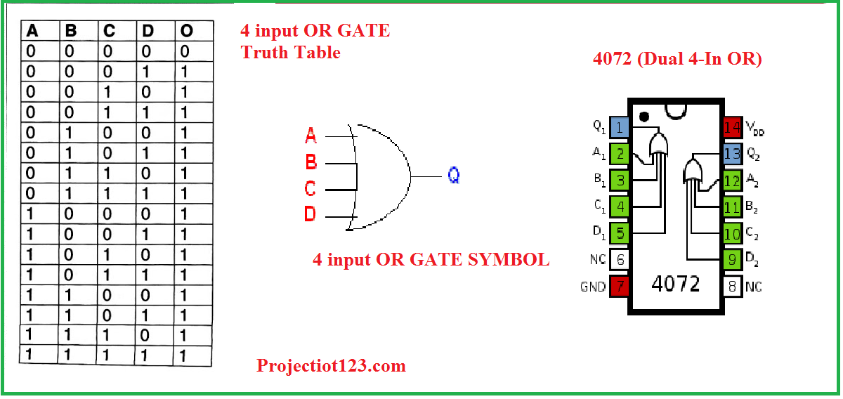
- 4072 Dual 4-lnput OR Gate
[otw_is sidebar=otw-sidebar-2]
4 input OR gate truth table
The Truth Table of the 4 input NOR Gate along with its schematics symbol is shown below:
That is all for now I hope this article would be helpful for you in the next article I will come up with NOT gate. Stay connected, keep reading and enjoy learning.