
tl494 pwm ic pinout application examples working smps 25
in this article we will learn tl494 pwm ic pinout application examples working smps.Hope you will be doing excellent. Today we will discuss about Integrated circuit TL494. Basically tl494 is a complete PWM power control circuit. The abbreviation of PWM is “Pulse Width Modulation”. The tl494 consist of two errors amplifiers. The one is on chip adjustable oscillator and the other is dead-time control comparator DTC. Tl494 can easily control flip-flop, a 5V circuit and output control circuit. TL494 is use in our everyday life. Such application is microwaves ovens, our computer desktop etc. If we talk about inverters the tl494 is also use in it. Such as smoke detectors, fire detectors power supplies AC and DC.
[otw_is sidebar=otw-sidebar-1]
TL494 Pin out:
- TL494 has total 16 pins and each pin has its own significant.
- The pin num 1 is connected to operation amplifier which has non inverting input.
- The pin num 2 is inverting input. He pin num 3 is feedback.
- The pin num 4 is DTC which is dead time control.
- The pin num 5 is CT and pin 6 is RT both is connecting with oscillator. CT means capacitor timing and RT means resistor timing both can control the frequency which add the oscillator that oscillator IC can walk.
- The pin num 7 should be ground.
- The pin num 8 and 9 is the internal transistor which is a collector meter.
- The first transistor which has C1 is collector and E1 is emitter.
- The pin num 10 and 11 is also a transistor. The pin num 12 is VCC which is the positive power supply to the IC.
- The pin num 13 is output control. The IC has a special feature it can use as a single ended and the push pull operation.
- The pin num 14 is 5v ref. The pin num 15 and pin num 16 is connected to operation amplifier which has non inverting input.
PIN-3 Feedback:
The output pulse width varies from 97% to 0 as voltage varies from 0.5v to 3.5v.
PIN-4:
Dead time control comparator input. It provides control of the minimum dead time. Dead time means off time. The output of the transistor is inhabits. Internally the pin is set to 3% with DTC and connecting to ground. The minimum range of DTC is between 3 percentages to 100 percentages varied.(tl494 pwm ic)
Block diagram of TL 494
I wil show you the simulation iin proteus by using TL494. Before staring our project we are using these following components.
- Resistor
- Capacitor
- Protentometer
- TL494
- LED light
- Oscilloscope
So let’s over view the components.
Resistor:
The reisitor is the most common electronics components in the word. It is used in practically everything. It’s used in setting operational amplifiers, getting the feedback loop setup, voltage dividers, current limiters for led’s and so many other things. The resistor symbol is actually very straightforward. In the picture you see. The first is in Europe symbol and the second one is Americans symbols. But they are actually quite similar. Resistors come in all shapes and sizes. Basicallly resistors can easily control the flow of electricity. For example if the current is passing through a pipe. When the pipe gets smallerthe current will struggle to get through it. So we can says that bigger pipe means lower resistance and smaller pipe means higher resistance. Less current flow using through it. According to Ohm’s law
V=IR
Where voltage equals to current time resistance.
Capacitor:
“A capacitor can stores energy by storing charges.” Capacitor having inside two pieces of conducting material like metals. But they are separate from each other. These metal pieces are cover with a paper so that metal don’t touch. If we connect a battery with capacitor the negative charges on the rght side get attracted towards the positive terminals of the battery. And on the lift side the negative charges get repelled away from the negative terminals of the batterry.
The SI unit is farad. Formula is
Q=CV
Potentometer:
- A potentiometer is a instrument used for the measurment of potential differernce accuratly.
- It consist of 10m long uniform wire manganin or constantan. Each of one meter length.
- It is based on the fact that potential drop in a wire of uniform reisitance is directly proportional to its length.
- At constant current flow through a wire having uniform area. So V is directly proportional to length.
TL494
- Basically tl494 is a complete PWM power control circuit. The abbreviation of PWM is “Pulse Width Modulation”.
- The tl494 pwm ic consist of two errors amplifiers.
- The one is on chip adjustable oscillator and the other is dead-time control comparator DTC. Tl494 can easily control flip-flop, a 5V circuit and output control circuit. TL494 is use in our everyday life. Such application is microwaves ovens, our computer desktop etc.
- If we talk about inverters the tl494 pwm ic is also use in it. Such as smoke detectors, fire detectors power supplies AC and DC. TL494 has total 16 pins and each pin has its own significant.
LED light :
Led is a light emitting diode having doped P-N junction. It is used to emit light. It convert electrical signals into light signals. It is used in forward bias and in reverse bias it works similar to normal pn junction diode. So the p junction is on anode side and the oher n junction is on cathode side. P type material is having holes as a mojarity carries and n type material having electrons as a majority carries. The junction that will be space charge region or in other words depletion region. When the electrons goess to the p juncion the holes accpte the electron and on the junction side it will get negative charge on it. And on the other hand n junction the holess will go on electron and junction get positive charges. The junction charges will callled a potential barries. It does not allow cuurent too pass from p type material to n type materials.
Symbol of led:
Oscilloscope:
The oscilloscope is the most important tool in electron circuits. It is widely used for investigating and debugging electronic circuits.They can be used to dibug, test, troubleshoot, a wide ranging problem. A multi meter is also an important test equipment but they can ony show the value of current, reisitance. But with the osciloscope you able to look varies waveforms. They give to a clear presentation on screen. This wil elp us to find the problem more easily. You can see the waveform start from x-axis amplitude on vertical axis time on the horizantal axis to y-axis. This is display on yur osciloscope.screen.
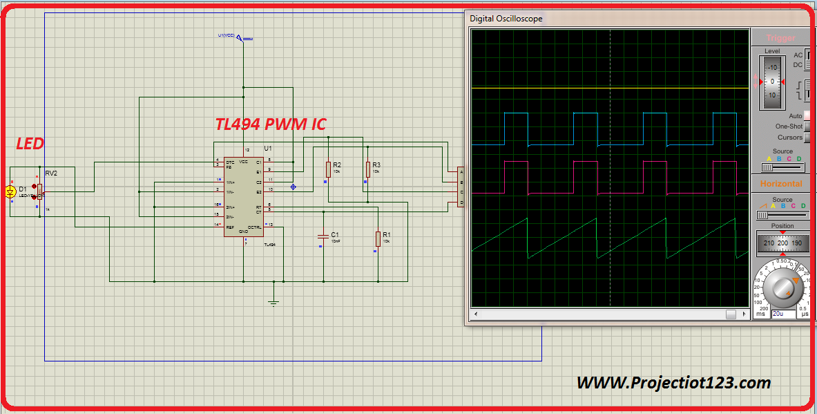
Simulation of our project
Waveform
If we talk about second waveform the output pulse width varies from 97% as voltage varies in 0.5v. If we increase the value of potentiometer the distance between waveform is wider. If we give 3.5v on third waveform the pulse rate will be minimum and there will be less distance between the upper transistor and lower transistor waveform. On the other hand first and fourth waveform did not change because it does not lies in range so that’s why it will be zero.
So this is our todays topic..
Hope you enjoy this and hope it will be helpful for you