
PIR sensor library for proteus 17
[otw_is sidebar=otw-sidebar-1]In this post I will discuss the simulation of the PIR sensor in the Proteus. In the previous post I have discussed the simulation of the Flex sensor in the Proteus. So this post is oriented around the procedure of the simulation of the Flame sensor and the PIR sensor in the Proteus.
After reading this post you will learn about the simulation model, importance of the simulation model in the library of Proteus, simulation of the flame sensor and the PIR sensor in the Proteus. So sit back, keep reading and enjoy learning
PIR Sensor:
[otw_is sidebar=otw-sidebar-3]
PIR (Passive Infrared) sensor is also known as the motion sensor which measures the Infrared (IR) light radiating from the object in its field of view. So when the object comes in its field of view the reading of the sensor gets disturbed and thus detect the presence the object in front of it. The PIR sensor looks like the one in the following figure:
PIR simulation in the Proteus:
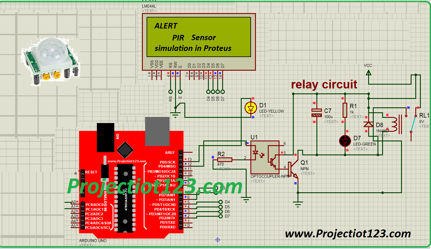
Now let us consider the simulation of the PIR sensor in the Proteus. As we have learned in case of the Flame sensor that in order to simulate the behavior of the component you need to install the simulation model of that component in the library of the software. The simulation model of the PIR sensor is not available in the library of the Proteus so we first need to download the files containing the simulation model of the PIR sensor. After downloading the simulation model then add the files containing the simulation model in the library of the Proteus. Now draw the circuit as shown in the following figure:
[otw_is sidebar=otw-sidebar-3]
Notice as shown in the above figure that the PIR sensor is connected to the Arduino at PIN number 2. Whenever the test pin in the above figure of the PIR sensor is asserted which actually mocks the presence of the body in front of the sensor the LED goes HIGH and the Arduino gives the reading on the Virtual terminal. The running simulation is as shown in the following figure:
[/vc_column_text][/vc_column][/vc_row][vc_row][vc_column][vc_btn title=”download this file” style=”classic” color=”green” link=”url:http%3A%2F%2Fprojectiot123.com%2F2019%2F03%2F10%2Fultrasonic-sensor-library-in-proteus%2F|title:flex%20sensor%20library%20for%20proteus|target:%20_blank|”][/vc_column][/vc_row]
The code for the above system is shown in the following :
[otw_is sidebar=otw-sidebar-2]
#define pirPin 2

    int calibrationTime = 30;
    long unsigned int lowIn;
    long unsigned int pause = 5000;
    boolean lockLow = true;
    boolean takeLowTime;
    int PIRValue = 0;

    void setup()
    {
    Serial.begin(9600);
    pinMode(pirPin, INPUT);
    }

    void loop()
    {
    PIRSensor();
    }

   void PIRSensor()
{
     if(digitalRead(pirPin) == HIGH)
     {
         if(lockLow)
         {
             PIRValue = 1;
             lockLow = false;
             Serial.println("Motion detected.");


             delay(50);
         }
         takeLowTime = true;
       }

       if(digitalRead(pirPin) == LOW)
       {

           if(takeLowTime){lowIn = millis();takeLowTime = false;}
           if(!lockLow && millis() - lowIn > pause)
           {
               PIRValue = 0;
               lockLow = true;
               Serial.println("Motion ended.");

               delay(50);
           }
       }
}