
Servo Motor Arduino Circuit Pinout Proteus Library Leave a comment
[otw_is sidebar=otw-sidebar-1]In this tutorial Servo Motor in Proteus, I will talk you how to execute a Controlled Servo Motor using Arduino. Using this project, you can manage a servo motor. We can also discuss the principle of servo motor, circuit diagram and working of this motor. So let’s start out lesson.
Principle of Servo Motor
Servo Motors are basically DC Motors with addition circuit that support in achieving precise position of the servo motor. In order to manage the rotation of the servo motor’s shaft, you require a special signal called Pulse Width Modulation signal.
Depending on the width of the pulse, the position of the servo motor differs. There are various ways in which you can create the PWM Signal to control a Servo Motor. The normal way is to use fully analog circuits like the Timer IC and using a potentiometer to manage the width of the pulse.
But with the help of Arduino, you can create PWM Signals without any outside components.
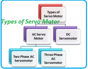
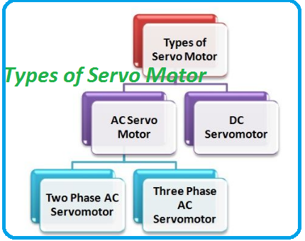
Types of Servo Motor
These motors are classified into various types depends on their application like Brushless DC, continuous rotation, linear and specific positional rotation, etc. Typical servo motors consist of three wires such as power, control, and ground. The outline and dimension of these motors based on their applications. The most common motor is an RC servo motor utilize in applications like robotics, reliability and comfortable of control by microprocessors.
 Components Required
Potentiometer
Servo Motor
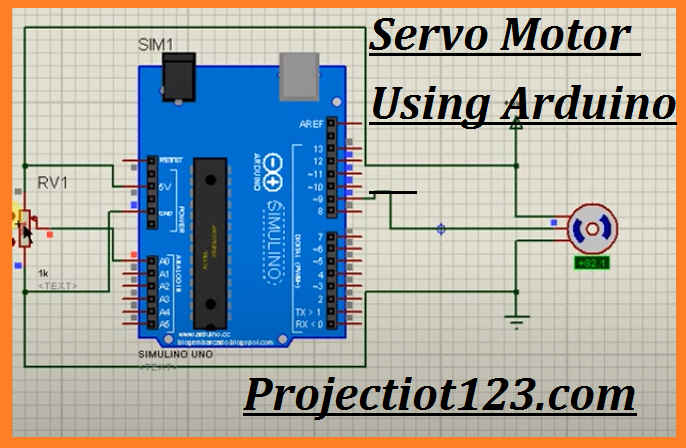
Servo Motor in Proteus
In this project first select all the components from the proteus libraries. After this we have to connect all the components. The servo motor has 3 pins. Its first pin is attached to 5v. Second pin is attached to Arduino pin 9 and the third pin is Ground. On the other hand potentiometer positive pin is connected to Arduino 5v and negative side is connected to Ground. After connecting all the components next step is simulate the project.
Working of Servo Motor
The servo motor has some control circuits and a potentiometer attached to the output shaft. If the shaft is at the right angle, then the motor shuts down. If the circuit sees that the angle is not correct, it will turn the motor until a desired angle. The output shaft of the servo have ability of traveling somewhere around 180 degrees. Generally, it is somewhere in the 210-degree varies; however, it range depending on the manufacturer. A simple servo is used to manage an angular motion of 0 to 180 degrees.
The power applied to the motor is proportional to the distance it required to travel. So, if the shaft required turning a large distance, the motor will run at full speed. If it required turning only a small amount, the motor will run at a slower speed. This is known as proportional control.
Applications of Servo Motor
- This motor can be utilized to manage the robotic vehicle by controlling robot speed, create plenty torque to move and also start and stop the robot.
- Servo Motor is highly cost-effective.
- Servo Motor has compact size.
- Servo Motor has quick response and high speed.
So this is it now days. We will meet you guys in next tutorial. Till than have fun.
Servo Motor Arduino Circuit Pinout Proteus Library