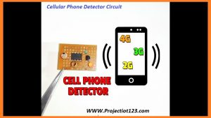
Cellular Phone Detector Circuit Diagram Leave a comment
 These days I even have style a Cellular Phone Detector Circuit Diagram. During this lesson we are going to discuss concerning the principle of this circuit, circuit diagram, limitation of this circuit and at the last we are going to discuss the applications. Let’s begin.
Cellular Phone Detector Circuit Diagram
[otw_is sidebar=otw-sidebar-1]
The most common equipment used now-a-days is cellular phone or portable. With advancement in communication technology, the necessity of cell phones has accrued dramatically. A cellular phone usually transmits and receives signals within the frequency vary of zero.9 to 3GHz. this text provides an easy circuit to discover the presence of AN activated cellular phone by police investigation these signals. I have designed 2 circuits that act as cellular phone Detector Circuit, one employing a combination of Scotty Diode and a Voltage Comparator and therefore the alternative employing a BICMOS Op-Amp.
Principle of Phone Detector Circuit
The basic principle behind the cellular phone Detector circuits is to discover the RF Signals. Within the Scotty diode circuit, the Scotty Diode is employed to discover the cellular phone signal as they need a novel property of having the ability to rectify low frequency signals, with low noise rate. Once AN electrical device is placed close to the RF signal supply, it receives the signal through mutual induction. This signal is corrected by the Scotty diode. This low power signal may be amplified and won’t to power any indicator like a junction rectifier during this case.
Components Required
NPN semiconductor unit
LM386
Battery
Diode
Circuit Design of Cellular Phone Detector
The main component is Amplifier. It consists of 8 pins. On the left side pin 2, 3 are connected to diode and 2 diodes are attached with functional machine. Amplifier pins 1, 8 are connected with resistor and capacitor are connected in its parallel. The remaining pins of amplifier are connected with LED and Battery.
Working of Cellular Phone Detector Circuit Diagram
In traditional condition, once there’s no RF signal, the voltage across the diode are negligible. Even supposing this voltage is amplified by the semiconductor unit electronic equipment, nonetheless the output voltage is a smaller amount than the reference voltage, which is applied to the inverting terminal of the comparator. Since the voltage at non inverting terminal of the OPAMP is a smaller amount than the voltage at the inverting terminal, the output of the OPAMP is low logic signal. Now once a portable is gift close to the signal, a voltage is evoked within the choke and therefore the signal is demodulated by the diode. This input voltage is amplified by the common electrode semiconductor unit. The output voltage is specified it’s over the reference output voltage. The output of the OPAMP is therefore a logic high signal and therefore the junction rectifier starts glowing, to point the presence of a portable. The circuit has got to be placed centimeters far away from the article to be detected.
long range mobile phone detector circuit
Applications of Cellular Phone Detector Circuit
- This circuit may be used at examination halls, conferences to discover presence of mobile phones and stop the utilization of cell phones.
- It may be used for police investigation mobile phones used for spying and unauthorized transmission of audio and video.
- It may be wont to discover taken mobile phones.
Limitations of movable Detector Circuit
- it’s a coffee vary detector, of the order of centimeters.
- The Scotty diode with higher barrier height littler amount sensitive to small signals.
So this is often all for these days. Hope you prefer this lesson. See you in next lesson. Bye.


