
nodemcu esp8266 library for proteus Leave a comment
[otw_is sidebar=otw-sidebar-1]Hi Friends In this projectiot123 article we will study nodemcu esp8266 library for proteus .It’s just for pcb .It’s not for simulation .In this tutorial I will tell you step by step and how to install it. My last post was about ESP8266 Web Server for Beginners.Note is a WiFi module that allows you to do WiFi communication and interfacing. You can also use it for like arduino.
You can download it easily, which is written below
[otw_is sidebar=otw-sidebar-2]
MQTT Protocol
nodemcu esp8266 library for proteus
[otw_is sidebar=otw-sidebar-3]
Step1
The file you download will be in the zip file
Step2
After downloading, divide it and put it in the proteus folder.
Step3
You will add the folder containing this library to the folder containing the library of Proteus.
Step4
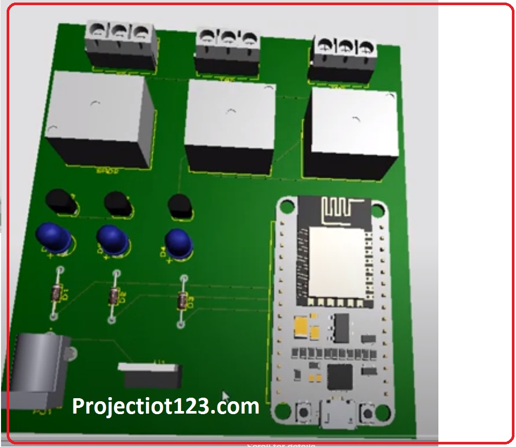
You can see in the picture it is only for PCB.No one has created a simulation yet, I will upload as soon as it is made.
The name of the wifi chip that is installed in the note is esp8266
Step5
Different models come in it, now we are using it right here
you can see how to relay interfacing with arduino UNO in proteus. my last post is what is relay
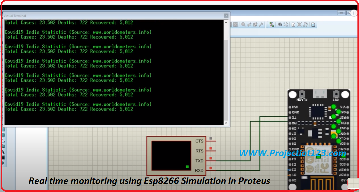
Real time monitoring using Esp8266 Simulation in Proteus
NodeMcu files Installation in Proteus
NodeMCU in Proteus || for Schematic & PCB design Only
esp8266 12e proteus library
[otw_is sidebar=otw-sidebar-2]
- proteus library zip file download
- esp8266 library for proteus 8 download
- nodemcu esp8266 library for proteus 8 download
Download from google drive link
In this post GETTING STARTED WITH ESP-NOW ESP8266 WITH ARDUINO IDE and ESP8266 NodeMCU boards.I will discuss about ESP-NOW and ESP8266 NodeMCU boards WITH ARDUINO IDE. In the last post I have discussed about the ESP8266 static IP address and MAC address and there I have mentioned that ESP8266 static IP address due to the limitation of the manufacturing technologies are subjected to some esp boards and these esp boards effects the Operation of the practical ip address circuits.
After reading this post you will learn about the GETTING STARTED WITH ESP-NOW ESP8266 WITH ARDUINO IDE .So sit back, keep reading and enjoy learning.
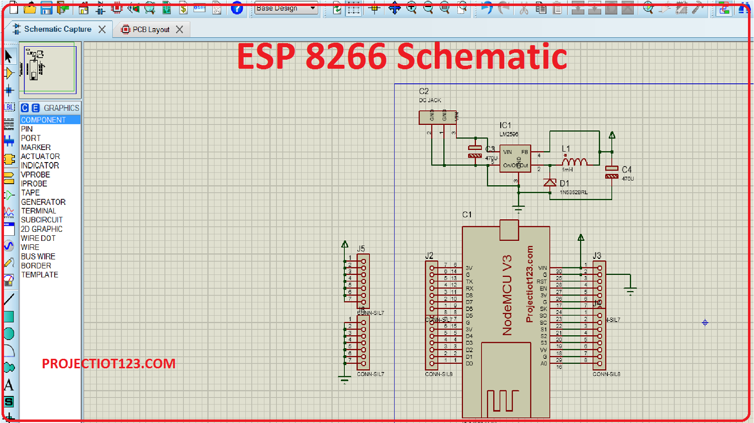
Esp8266 Schematic
here is a esp8266 schematic for pcb
esp8266 data logger using thingspeak
here is the circuit of esp8266 data logger using thingspeak with pcb

Components Required for esp8266 data logger
- Node MCU8266
- Micro SD Card Module
- Male to Female jumper wire
-
DS1307 RTC Module(Real Time clock)
-
Battery Backup Cell for rtc module
- lithium battery charger
- lithium battery 3.7 voltage
- diode 4007
- resistor
- capcitor
- Different Types Connectors
Introduction of ESP01
The first chip in this series was introduced as ESP-01 that gained a complete attention in the market but it created hurdles because the language was in Chinese. Afterward many features are added to this device that mostly comes with English language. It is easy to utilizes and even an average person can easily understand and make their feet wet with the study of this device.
ESP01 Pinout
ESP8266 is very easy to use, features low cost and develops an easy TCP connection by joining microcontrollers with WIFI. It has capacity to hosting all WIFI function to other processors. ESP8266 is a user friendly WIFI device that supports both TCP and microcontrollers. It works at 3V with maximum voltage varies around 3.6V. It can be interfaced with the sensors and other module and needs very little modification and development to make it capable with other devices.
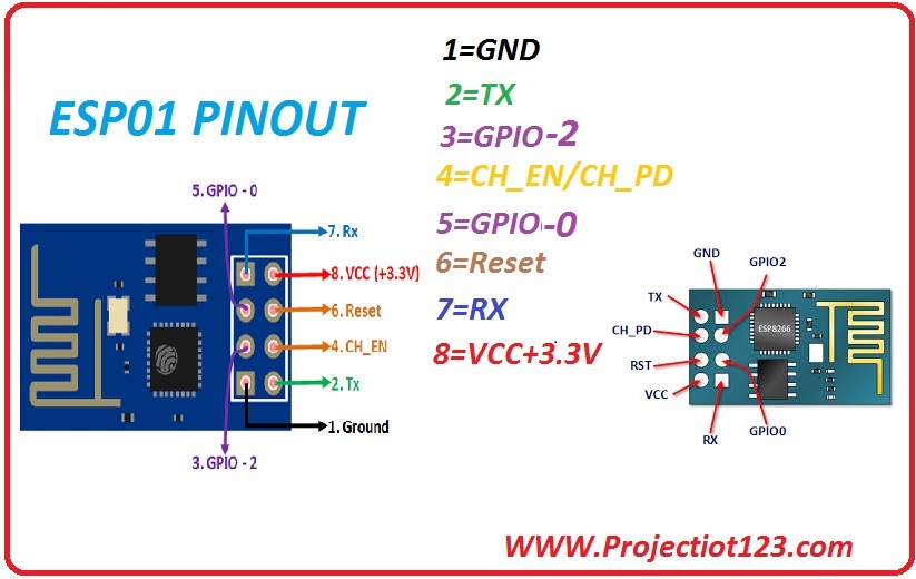
Pin Configuration
| Pin No. | Pin Name | Description |
| 1 | GND | Connect to the ground |
| 2 | TX | Connected to Rx pin of programmer |
| 3 | GPIO-2 | General purpose Input& output pin |
| 4 | CH-EN | Chip Enable |
| 5 | GPIO-0 | General purpose Input& output pin |
| 6 | Reset | Reset the device |
| 7 | RX | General purpose Input& output pin |
| 8 | Vcc | Connect to +3.3v |
ESP8266 Arduino Interface:
Today we convey our message to each other by using mobile phones, which is a wireless communication gadget. It gives us relief to communicate with our friends at any place and at any time. How we can share our data to a machine from a distance wirelessly. It is possible by using this ESP8266 WIFI device. The current trends in the Lot sector request us for control the internet and WIfI is a main facilitator of that feature.
Components Required:
Arduino
Potentiometer
ESP8266
Explanation
The ESP8266 is a WIfI component that can be controlled from your internet. It is a component that uses WIFI automation to send and receive data wirelessly. It uses radio wave to send and receive data. ESP8266 can work both as an initial point and also as a station.
WIFI is a radio technologies mostly used for wireless local area networking devices. It uses radio waves to gives network connectivity without the use of any cables either wires. It must have three devices that are radio signals, antenna, and router.
The ESP-01 component forms a gateway between the Arduino and the internet. It acts as a focal point that receives data and then sends this data to the Arduino. The antenna transmits the radio waves, and inbound signals are hold up by WIFI receivers. Hence, it can communicate with both 2.3 GHz devices and 5 GHz devices.
Applications
Some cool applications are listed below
- Home management system.
- Drone control
- Smart home application
- IOT project
- Wireless data logging
ESP8266 BOARD LED BY USING ADAFRUIT MQTT BROKER