
L298 Motor Driver Simulation in Proteus 47
[otw_is sidebar=otw-sidebar-1]In this post I will discuss about the simulation of L298 motor driver in Proteus. In the previous posts I have discussed about the Bluetooth module simulation in Proteus and also have discussed important sensors and actuators in Proteus. This post will be oriented around the L298 motor driver and its simulation in Proteus.
After reading this post the reader will be able to learn about the basics of the L298 motor controller, working of the L298 motor controller, the principle of the L298 motor controller, circuit for L298 motor controller, interfacing of the Arduino microcontroller development board with L298 motor driver in Proteus. So sit back, keep reading and enjoy learning.
[otw_is sidebar=otw-sidebar-2]
L298 Motor driver
- L298 is basically the Integrated Circuit chip that is used to drive the DC motors.
- The chip is designed in such a way so as to control two DC motors simultaneously and in addition control the direction of rotation of each motor
- I will go into detail about this later in this post. The L298 chip looks like the one in the following image:

- The L298 IC is a high current, high voltage full bridge driver designed to accept the standard TTL (Transistor-Transistor Logic) logic. The chip is optimized to drive the inductive loads such as relays, solenoids and DC motors.
- The Block diagram of the L298 motor driver IC is as shown in the following image:
[otw_is sidebar=otw-sidebar-3]

As can be see that there are four input pins and four output pins along them two Enable pins are also available in chip. The working of each of the pin will be discussed in the following section.
Pin Configuration of the L298 Motor Driver IC
- The pinout of the chip is as shown in the following table:
- The above table describes the functionality of the pins of the L298 motor driver IC.
- Let us learn about each bridge of the IC and its pins in some more detail. In order to understand the working of each bridge of the IC consider the following circuit:
- The circuit in the above figure is called the H-Bridge circuit and is used to control the direction of rotation of the motor. Each input of the bridge lets the motor to rotate in either clockwise or counter-clockwise rotation.
- The enable pin of the motor driver IC that is the ENA and ENB enables the bridge inside the IC.
Why need the L298 Motor Driver?
How to use L298n Motor Driver
- A question arises that why do we need the Motor Driver in fact we can drive the motor by Arduino nano or any other microcontroller?
- The answer to this question is very simple that the Arduino or any other microcontroller cannot supply enough current to drive the motors so we need the separate circuit that drives the motor itself.
[otw_is sidebar=otw-sidebar-2]
L298n Motor Driver Specification
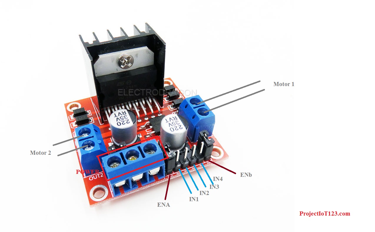
- As we saw in the previous discussion that the L298 is the motor driver IC but usually it is available in the modular form which is ready to plug and play. The module of L298 motor driver looks like the one in the following image:
- The control pins, output pins and the power pins are available at the connectors of the module. Let us consider the working if each pin in detail.
INPUT1 pin of l298n
This pin along with the INPUT2 pin is used to control the direction of the motor 2.
INPUT2:
This pin along with the INPUT1 pin is used to control the direction of the motor 2.
INPUT3:
This pin along with the INPUT4 pin is used to control the direction of the motor 1.
INPUT4:
This pin along with the INPUT3 pin is used to control the direction of the motor 1.
ENABLEA:
This pin is used to enable the driver of the motor 2. This pin is made HIGH by default in module with the help of the jumper.
ENABLEB:
This pin is used to enable the driver of the motor 1. This pin is made HIGH by default in module with the help of the jumper.
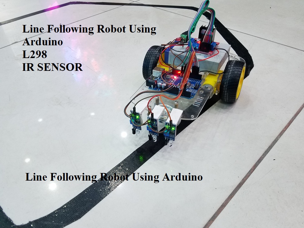
Line Following Robot Using Arduino:
in this project i will tell you how to make Line Following Robot Using Arduino which is used arduino uno smd board.this project we used parts as follow
- Arduino Uno smd
- l298 H bridghttps://projectiot123.com/2019/04/07/arduino-uno-for-beginners/e
- IR Proximity Sensors x3
- batteries 4 volt x2 in series
- connecting wires
- switch on/off
- 2 wheel car Chassis
Line Following Robot Using Arduino and l298:
Line Following Robot circuit diagram:
Here is the circuit diagram of Line Following Robot

Line Following Robot Using Arduino Code:
Here is the code of Line Following Robot
int S_A = 10;  //speed motor a
int M_A1 = 2; //motor a = +
int M_A2 = 3; //motor a = -
int M_B1 = 4; //motor b = -
int M_B2 = 5; //motor b = +
int S_B = 9;  //speed motor b

int R_S = A0; //sincer R
int S_S = A1; //sincer S
int L_S = A2; //sincer L

void setup()
{
pinMode(M_B1, OUTPUT);
pinMode(M_B2, OUTPUT);
pinMode(M_A1, OUTPUT);
pinMode(M_A2, OUTPUT);
pinMode(S_B, OUTPUT);
pinMode(S_A, OUTPUT);

pinMode(L_S, INPUT);
pinMode(S_S, INPUT);
pinMode(R_S, INPUT);

analogWrite(S_A, 150);
analogWrite(S_B, 150);
delay(200);
}
void loop()
{
if ((digitalRead(L_S) == 0)&&(digitalRead(S_S) == 1)&&(digitalRead(R_S) == 0)){forword();}

if ((digitalRead(L_S) == 1)&&(digitalRead(S_S) == 1)&&(digitalRead(R_S) == 0)){turnLeft();}
if ((digitalRead(L_S) == 1)&&(digitalRead(S_S) ==0)&&(digitalRead(R_S) == 0)) {turnLeft();}

if ((digitalRead(L_S) == 0)&&(digitalRead(S_S) == 1)&&(digitalRead(R_S) == 1)){turnRight();}
if ((digitalRead(L_S) == 0)&&(digitalRead(S_S) == 0)&&(digitalRead(R_S) == 1)){turnRight();}

if ((digitalRead(L_S) == 1)&&(digitalRead(S_S) == 1)&&(digitalRead(R_S) == 1)){Stop();}
}

void forword(){
digitalWrite(M_A1, LOW);
digitalWrite(M_A2, HIGH);
digitalWrite(M_B1, HIGH);
digitalWrite(M_B2, LOW);
}


void turnRight(){
digitalWrite(M_A1, LOW);
digitalWrite(M_A2, LOW);
digitalWrite(M_B1, HIGH);
digitalWrite(M_B2, LOW);
}

void turnLeft(){
digitalWrite(M_A1, LOW);
digitalWrite(M_A2, HIGH);
digitalWrite(M_B1, LOW);
digitalWrite(M_B2, LOW);
}

void Stop(){
digitalWrite(M_A1, LOW);
digitalWrite(M_A2, LOW);
digitalWrite(M_B1, LOW);
digitalWrite(M_B2, LOW);
}
POWER SUPPLY OF l298n motor driver;
Two power supplies with common ground is used to power up the module. One of the powers is logic supply and should be 5V and the other could be 12 volt ir according to requirement. See datasheet for detail.
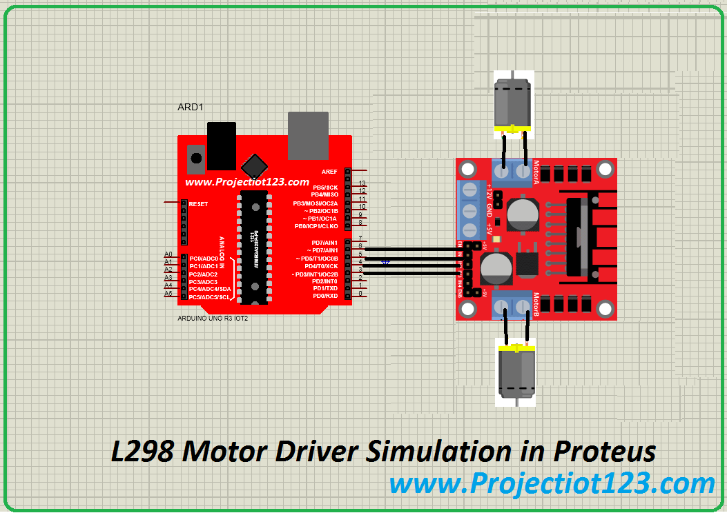
L298 Simulation in Proteus
- The discussion in the previous sections describes the working of the L298 bridge motor driver. Let us now simulate the behavior of the L298 module in the Proteus.
- It is important here to mention that it is always beneficial to simulate the circuit before actually implementing the hardware.
- By simulating the system the designer can look for the glitches in the code or errors in the circuit. So it saves both time and money.
- It is important to note here that if you want to simulate the behavior of any circuit it is necessary that the simulation models of all of the electronic components that are used in the circuit should be present in the library of the software used for simulation.
- If the simulation model of the component is not present in the library of the software the software will be unable to simulate the behavior of the entire circuit.
- The simulation model of the L298 chip is already available in the Proteus. Bit I am using the modular simulation model of the L298 motor driver.
- You need to download the files containing the simulation models of the motor driver and place them in the library of the Proteus, Go through my post on Ultrasonic sensor I have discussed the whole procedure there.
[otw_is sidebar=otw-sidebar-3]
Step1:
Place all the components in the workspace of the Proteus as shown in the following figure:
Arduino Interfacing with l298n Step2:
Now connect the Arduino and l298 circuit as shown in the following figure:
As can be seen in the figure that the all the control pins are connected to the digital input / output pins of the Arduino microcontroller board.
Step3
Attach the HEX file of the code of the Arduino in Proteus as shown in the following figure:
Step4
Hit the simulation button to initiate the animation:
[otw_is sidebar=otw-sidebar-2]
L298 Motor Driver Arduino Code:
in this project we are control 2 dc motors using l298 h bridge with arduino code. You can compile and download in Arduino
/*
  Blink
  Turns on an LED on for one second, then off for one second, repeatedly.

  This example code is in the public domain.
 */


 #include <LiquidCrystal.h>

LiquidCrystal lcd(13, 4, 12, 11, 10, 9);
//                BS  E  D4 D5  D6 D7

// Pin 13 has an LED connected on most Arduino boards.
// give it a name:
int st1 = 5;
int st2 = 6;
int st3 = 7;
int st4 = 8;
int led = 13;
int cnt=0;
int b1 = 2;//
int b2 = 3;
int an0 = A0;
int pos1;
long cnt5=0;
int val;
// the setup routine runs once when you press reset:
void setup() {
  // initialize the digital pin as an output.
  pinMode(st1, OUTPUT);
  pinMode(st2, OUTPUT);
  pinMode(st3, OUTPUT);
  pinMode(st4, OUTPUT);
  pinMode(led, OUTPUT);

 pinMode(b1, INPUT_PULLUP);
 pinMode(b2, INPUT_PULLUP);

digitalWrite(st1, HIGH);
digitalWrite(st2, HIGH);
digitalWrite(st3, HIGH);
digitalWrite(st4, HIGH);
  Serial.begin(9600);
  Serial.println("WELL COME" );
  pinMode(an0, INPUT);
lcd.begin(16, 2);
lcd.setCursor(0, 0);  lcd.print("WELL COME ");
delay(500);
lcd.clear();


}

// the loop routine runs over and over again forever:
void loop() {

lcd.setCursor(0, 0);  lcd.print("STOP ");
stop1();
delay(500);
   if(digitalRead(b1) == LOW){
  while(digitalRead(b1) == LOW){
lcd.setCursor(0, 0);  lcd.print("FORWARD ");
//delay(500);
  fwd();
}
lcd.clear();

}
   if(digitalRead(b2) == LOW){
   while(digitalRead(b2) == LOW){
lcd.setCursor(0, 0);  lcd.print("REVERSE ");
//delay(500);
    rev();
}
lcd.clear();
   }
  }
void fwd(){
digitalWrite(st1, LOW);
digitalWrite(st2, HIGH);
digitalWrite(st3, LOW);
digitalWrite(st4, HIGH);
}
void rev(){
digitalWrite(st1, HIGH);
digitalWrite(st2, LOW);
digitalWrite(st3, HIGH);
digitalWrite(st4, LOW);}
void stop1(){
digitalWrite(st1, HIGH);
digitalWrite(st2, HIGH);
digitalWrite(st3, HIGH);
digitalWrite(st4, HIGH);}
we use these components
arduino dc motor forward reverse:
we are using lcd2x16 ,arduino uno r3,l298 motor driver ,push button and 2 dc motors
dc motor arduino code
That is all for now (L298 Motor Driver Simulation in Proteus) I hope this post would be helpful for you. In the next post I will come up with more interesting applications and simulations of the Proteus. Till then stay connected, keep reading and enjoy learning.