orcad allegro tutorial measure distance 7
[otw_is sidebar=otw-sidebar-1] Hey guys!I hope you all are good, this is fifth tutorial in the series of the “Introduction to Allegro PCB Designer”. In the previous tutorials I have discussed about the basic commands used frequently while developing the layout of the printed circuit board at beginners’ level; we have learned about the “Add Connect”, “Slide”, “Hilight”, “Dehilight” command and along with the proper application of the “Options” and “Find” window.
Note:
Cadence Allegro Tutorials
| LIST OF Cadence AllegroTurorials | Names |
| Tutorial # 1 | Introduction to Allegro PCB Designer |
| Tutorial # 2 | Allegro Use “Add Connect Tool” |
| Tutorial # 3 | Allegro Use “Slide Tool” |
| Tutorial # 4 | Allegro Use “Hilight & Dehilight Tool” |
| Tutorial # 5 | Allegro Use “Show Measure & Grid” |
| Tutorial # 6 | Introcution to Nets in Allegro |
| Tutoiral # 7 | Introcution to Stackup in Allegro |
| Tutorial # 8 | Introcution to Copper Shapes in Allegro |
| Tutorial # 9 | Introduction Vias and GND Plane in Allegro |
ALL Orcad Allegro Tutorial for Beginner Ask free to Question us
Introduction to Allegro PCB Designer (Part 5)
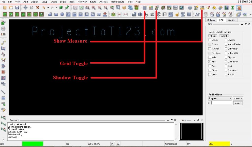
In this tutorial I will discuss in detail about other basic commands used at the beginners’ level, so two other basic commands used frequently at the basic level are “Show measure”, “Shadow Toggle”.
On the Graphical User Interface (GUI) of the Allegro PCB designer software these commands are shown at the top of the window as shown in the following image:
Let us first discuss about the Shadow toggle command.
Shadow Toggle:
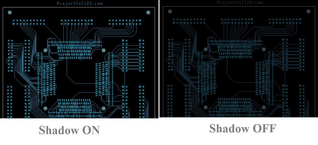
Shadow toggle is another important command that is used as the visual aid in order to see the complete layout of the printed circuit board. By Shadow Toggle it means that there are two options Shadow On and Shadow Off mode. While developing the layout of the PCB the Shadow Mode is kept off and the elements that are to be considered are highlighted or assigned a particular color but in order to have the overall look at the layout the Shadow mode is turned On. The following image shows the layout of the printed circuit board in both Shadow on and Shadow off mode.
As shown in the above image that the in Shadow ON mode the layout looks more visible. The Shadow is toggled just by left clicking on the “Shadow Toggle” icon, the “Options” and “Find” window are not involved for this command. The “Shadow Toggle” command automatically selects the entire board as shown in the above image.
Let us now discuss about the “Show Measure” command.
Shadow Measure:
The command is made activated by left clicking on the icon and the name of the command will appear at the bottom left corner of GUI when the command is activated as shown in the following image:
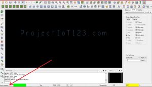 After the command is activated the command will display the message saying “Make two picks for the distance calculator”. Open the “Find” window as shown in the following image, you will say that some of the elements that are valid for the command “Show Measure” will appear prominent.
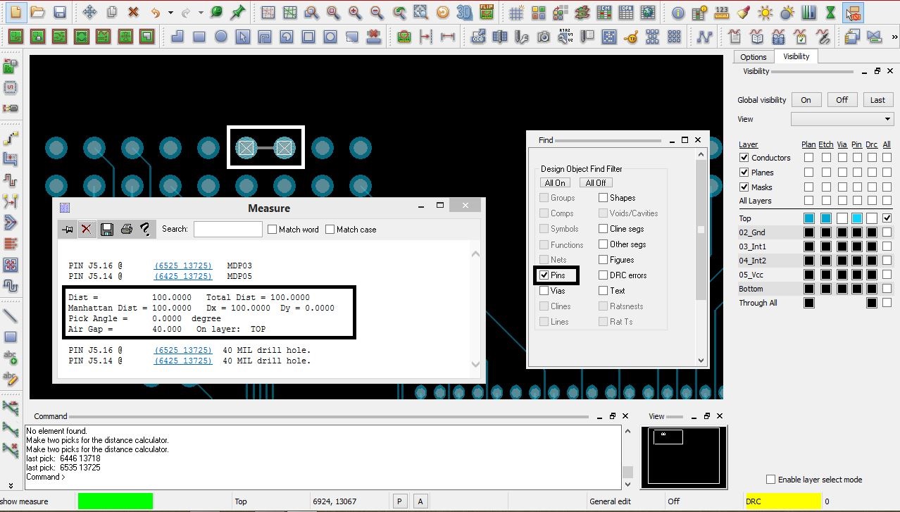
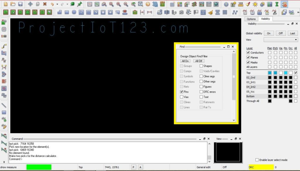 Recall from my previous tutorial that only the elements that are checked in the “Find” window will be selected and those that are not checked will not be selected. It is recommended to go through my first tutorial of the series in order to learn about the “Options” and “Find” window in detail. Let us come back to the “Show Measure” command, the “Show Measure” command is used to measure the distance between any two selected elements. For example the “Show Measure” can be used to measure the distance between two pins of the footprint of the electronic component, or it can also measure the distance between two vias, distance between nets and all those elements that are highlighted in the “Find” window. But remember that only the elements that are checked can be selected thus measure the distance. The distance is measured between two pins is measured by the “Show Measure” as shown in the following image;
orcad allegro tutorial measure distance
“Show measure” measures different distances for example “Dist” is the measure of the distance between two pins from their center points and “Air Gap” is the measure of the length of the gap between two pins from their edges. The above image represents the measured distances.
That is all for now, I hope this tutorial would be helpful for you. In the next tutorial I will dsicuss about the PCB stackup and application of the third window “Visibility”. Till then stay connected, keep reading and enjoy learning.

https://finasteride.store/# order cheap propecia price
https://finasteride.store/# cheap propecia without prescription
https://cytotec.club/# Misoprostol 200 mg buy online
http://ciprofloxacin.tech/# buy ciprofloxacin over the counter
cytotec abortion pill buy cytotec over the counter cytotec abortion pill
lisinopril 10 mg tablet price: prinivil 2.5 mg – lisinopril price
http://finasteride.store/# cost of generic propecia for sale