int sw1=8;
int sw2=9;
int sw3=10;
int sw4=11;
#include <LiquidCrystal.h>
LiquidCrystal lcd(7, 6, 5, 4, 3, 2);
#include <Wire.h>
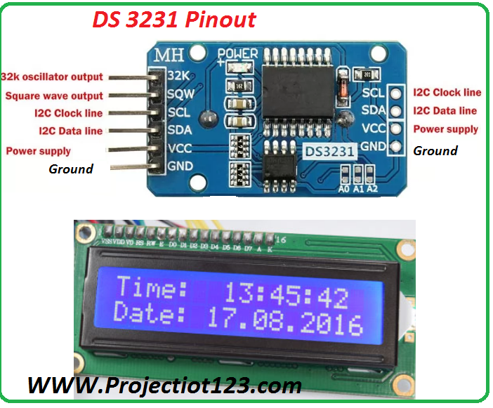
const int DS1307 = 0x68; // Address of DS1307 see data sheets
const char* days[] =
{“Sunday”, “Monday”, “Tuesday”, “Wednesday”, “Thursday”, “Friday”, “Saturday”};
const char* months[] =
//{“January”, “February”, “March”, “April”, “May”, “June”, “July”, “August”,”September”, “October”, “November”, “December”};
{“Jan”, “Feb”, “March”, “April”, “May”, “June”, “July”, “August”,”Septem”, “Octobe”, “Novem”, “Decemb”};
// Initializes all values:
byte second = 0;
byte minute = 0;
byte hour = 0;
byte weekday = 0;
byte monthday = 0;
byte month = 0;
byte year = 0;
void setup() {
Wire.begin();
lcd.begin(16, 2);
pinMode(sw1, INPUT_PULLUP);
pinMode(sw2, INPUT_PULLUP);
pinMode(sw3, INPUT_PULLUP);
pinMode(sw4, INPUT_PULLUP);
if(digitalRead(sw1) == LOW){
delay(100);
}
Serial.begin(9600);
delay(2000); // This delay allows the MCU to read the current date and time.
Serial.print(“The current date and time is: “);
printTime();
Serial.println(“Please change to newline ending the settings on the lower right of the Serial Monitor”);
Serial.println(“Would you like to set the date and time now? Y/N”);
/*
while (!Serial.available()) delay(10);
if (Serial.read() == ‘y’ || Serial.read() == ‘Y’)
// This set of functions allows the user to change the date and time
{
Serial.read();
setTime();
Serial.print(“The current date and time is now: “);
printTime();
}
*/
Serial.println(“Thank you.”);
}
// Continuous function for converting bytes to decimals and vice versa
void loop() {
printTime();
delay(500);
chk();
}
void chk(){
if(digitalRead(sw1) == LOW){
lcd.clear();
lcd.setCursor(0, 0);
lcd.print(“enter year setting”);
delay(500);
while(digitalRead(sw1) == LOW){delay(500); }
while(digitalRead(sw1) == HIGH){delay(500);
if(digitalRead(sw2) == LOW){
year++;
lcd.setCursor(10, 1);
lcd.print(year);
delay(300);
}
if(digitalRead(sw3) == LOW){
year–;lcd.setCursor(10, 1);
lcd.print(year);delay(300);
}}
lcd.clear(); delay(300);
///*
lcd.clear(); lcd.setCursor(0, 0);
lcd.print(“enter month”);delay(500);
while(digitalRead(sw1) == LOW){delay(500); }
while(digitalRead(sw1) == HIGH){delay(300);
if(digitalRead(sw2) == LOW){
lcd.setCursor(6, 1);
lcd.print(” “);
month++; lcd.setCursor(6, 1);
lcd.print(months[month-1]);delay(100);
}
if(digitalRead(sw3) == LOW){
month–;
lcd.setCursor(6, 1); lcd.print(” “);
lcd.setCursor(6, 1);
lcd.print(months[month-1]);delay(100);
}}
lcd.clear(); delay(300);
lcd.clear(); lcd.setCursor(0, 0);
lcd.print(“enter date”);delay(500);
while(digitalRead(sw1) == LOW){delay(500); }
while(digitalRead(sw1) == HIGH){delay(300);
if(digitalRead(sw2) == LOW){
lcd.setCursor(6, 1);
lcd.print(” “);
monthday++; lcd.setCursor(6, 1);
lcd.print(monthday);delay(100);
}
if(digitalRead(sw3) == LOW){
monthday–;
lcd.setCursor(6, 1); lcd.print(” “);
lcd.setCursor(6, 1);
lcd.print(monthday);delay(100);
}}
lcd.clear(); lcd.setCursor(0, 0);
lcd.print(“enter day”);delay(500);
while(digitalRead(sw1) == LOW){delay(500); }
while(digitalRead(sw1) == HIGH){delay(300);
if(digitalRead(sw2) == LOW){
lcd.setCursor(6, 1);
lcd.print(” “);
weekday++; lcd.setCursor(6, 1);
lcd.print(days[weekday-1]);delay(100);
}
if(digitalRead(sw3) == LOW){
weekday–;
lcd.setCursor(6, 1); lcd.print(” “);
lcd.setCursor(6, 1);
lcd.print(days[weekday-1]);delay(100);
}}
lcd.clear(); lcd.setCursor(0, 0);
lcd.print(“enter hour”);delay(500);
while(digitalRead(sw1) == LOW){delay(500); }
while(digitalRead(sw1) == HIGH){delay(300);
if(digitalRead(sw2) == LOW){
lcd.setCursor(6, 1);
lcd.print(” “);
hour++; lcd.setCursor(6, 1);
lcd.print(hour);delay(100);
}
if(digitalRead(sw3) == LOW){
hour–;
lcd.setCursor(6, 1); lcd.print(” “);
lcd.setCursor(6, 1);
lcd.print(hour);delay(100);
}}
lcd.clear(); lcd.setCursor(0, 0);
lcd.print(“enter minute”);delay(500);
while(digitalRead(sw1) == LOW){delay(500); }
while(digitalRead(sw1) == HIGH){delay(300);
if(digitalRead(sw2) == LOW){
lcd.setCursor(6, 1);
lcd.print(” “);
minute++; lcd.setCursor(6, 1);
lcd.print(minute);delay(100);
}
if(digitalRead(sw3) == LOW){
minute–;
lcd.setCursor(6, 1); lcd.print(” “);
lcd.setCursor(6, 1);
lcd.print(minute);delay(100);
}}
second=0;
//*/
// The following codes transmits the data to the RTC
Wire.beginTransmission(DS1307);
Wire.write(byte(0));
Wire.write(decToBcd(second));
Wire.write(decToBcd(minute));
Wire.write(decToBcd(hour));
Wire.write(decToBcd(weekday));
Wire.write(decToBcd(monthday));
Wire.write(decToBcd(month));
Wire.write(decToBcd(year));
Wire.write(byte(0));
Wire.endTransmission();
// Ends transmission of data
}
}
byte decToBcd(byte val) {
return ((val/10*16) + (val%10));
}
byte bcdToDec(byte val) {
return ((val/16*10) + (val%16));
}
// This set of codes is allows input of data
void setTime() {
Serial.print(“Please enter the current year, 00-99. – “);
year = readByte();
Serial.println(year);
Serial.print(“Please enter the current month, 1-12. – “);
month = readByte();
Serial.println(months[month-1]);
Serial.print(“Please enter the current day of the month, 1-31. – “);
monthday = readByte();
Serial.println(monthday);
Serial.println(“Please enter the current day of the week, 1-7.”);
Serial.print(“1 Sun | 2 Mon | 3 Tues | 4 Weds | 5 Thu | 6 Fri | 7 Sat – “);
weekday = readByte();
Serial.println(days[weekday-1]);
Serial.print(“Please enter the current hour in 24hr format, 0-23. – “);
hour = readByte();
Serial.println(hour);
Serial.print(“Please enter the current minute, 0-59. – “);
minute = readByte();
Serial.println(minute);
second = 0;
Serial.println(“The data has been entered.”);
// The following codes transmits the data to the RTC
Wire.beginTransmission(DS1307);
Wire.write(byte(0));
Wire.write(decToBcd(second));
Wire.write(decToBcd(minute));
Wire.write(decToBcd(hour));
Wire.write(decToBcd(weekday));
Wire.write(decToBcd(monthday));
Wire.write(decToBcd(month));
Wire.write(decToBcd(year));
Wire.write(byte(0));
Wire.endTransmission();
// Ends transmission of data
}
byte readByte() {
while (!Serial.available()) delay(10);
byte reading = 0;
byte incomingByte = Serial.read();
while (incomingByte != ‘\n’) {
if (incomingByte >= ‘0’ && incomingByte <= ‘9’)
reading = reading * 10 + (incomingByte – ‘0’);
else;
incomingByte = Serial.read();
}
Serial.flush();
return reading;
}
void printTime() {
char buffer[3];
const char* AMPM = 0;
readTime();
Serial.print(days[weekday-1]);
Serial.print(” “);
Serial.print(months[month-1]);
Serial.print(” “);
Serial.print(monthday);
Serial.print(“, 20”);
Serial.print(year);
Serial.print(” “);
if (hour > 12) {
hour -= 12;
AMPM = ” PM”;
}
else AMPM = ” AM”;
Serial.print(hour);
Serial.print(“y:”);
sprintf(buffer, “%02d”, minute);
Serial.print(buffer);
Serial.println(AMPM);
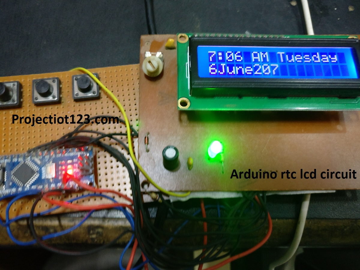
lcd.setCursor(0, 0);
lcd.print(hour);
lcd.print(“:”);
lcd.print(buffer);
lcd.print(AMPM);
lcd.print(” “);
lcd.print(days[weekday-1]);
lcd.setCursor(0, 1);
lcd.print(monthday);
lcd.print(months[month-1]);
lcd.print(“20”);
lcd.print(year);
}
void readTime() {
Wire.beginTransmission(DS1307);
Wire.write(byte(0));
Wire.endTransmission();
Wire.requestFrom(DS1307, 7);
second = bcdToDec(Wire.read());
minute = bcdToDec(Wire.read());
hour = bcdToDec(Wire.read());
weekday = bcdToDec(Wire.read());
monthday = bcdToDec(Wire.read());
month = bcdToDec(Wire.read());
year = bcdToDec(Wire.read());
}