
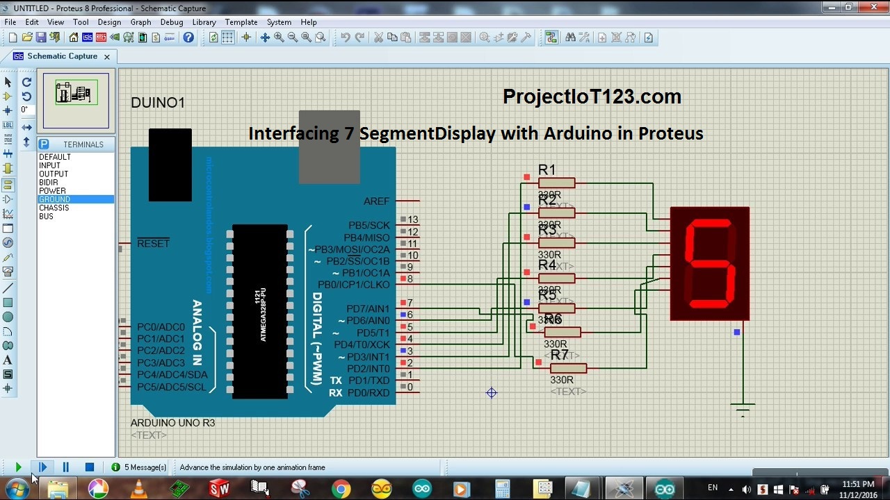
Interfacing 7 Segment Display with Arduino in Proteus 10
[otw_is sidebar=otw-sidebar-1]In this article I will discuss about Interfacing 7 Segment Display with Arduino in Proteus.and how to simulate the circuit containing Arduino interfaced with Seven Segment Display in Proteus. Seven segment display is simply a display for displaying the numeric data. It is commonly used in different kinds of timers, stop watches and desktops clocks. So in this article the discussion will be oriented around how to interface the Seven Segment Display with Arduino and simulate the code and circuit using Proteus. The configuration of the LEDs in the Seven Segment Display looks like the one in the image below:
[otw_is sidebar=otw-sidebar-2]

7 segment display pinout
[dt_gap height=”10″ /]
In the paragraphs to follow I will discuss the Seven Segment Display pinout(7 segment display pinout) , the pin out of the of the Seven Segment Displays, interface of Arduino and Seven Segment Displays, how to write code for the Seven Segment Display counting in Arduino and then finally simulate the circuit in the Proteus. So sit back, keep reading and enjoy learning of 7 segment display pinout

7 Segment Displays
As described in the above paragraph the Seven Segment Display or sometimes called the Seven Segment Indicator is a type electronic display that is used for displaying the numeric data. The seven segment display can be found in various applications such as digital clocks, electronic meters, calculators and other electronic circuits which need to display the numeric data to the user.
Note:Two types of Seven Segments are available in the market depending upon their internal construction
- Common anode Seven Segment Display.
- Common Cathode Seven Segment Display.
[otw_is sidebar=otw-sidebar-3]
The basic circuit of either of the display is same the only difference as clear by the name of each is that one is common anode with the data signals intended to applied on cathode pins and other is common cathode with data signals applied on the anode pins of the display. The pinout of the Seven Segment Display is shown in the figure below:
Interfacing 7 Segment Display with Arduino in Proteus
As represented in the figure each LED in the Seven Segment Display is denoted by the Alphabets a to g. These LEDs are turned on in the particular manner to display any numeral from 1 to 0. As also represented in the figure these LEDs are controlled by the Pin numbers specified for each LED.
The concept of the common anode can be seen in the following figure:
[/vc_column_text][/vc_column][/vc_row][vc_row][vc_column][vc_btn title=”download this file” style=”classic” color=”green” link=”url:http%3A%2F%2Fprojectiot123.com%2F2019%2F03%2F10%2Fultrasonic-sensor-library-in-proteus%2F|title:flex%20sensor%20library%20for%20proteus|target:%20_blank|”][/vc_column][/vc_row]
In the similar way the concept of the common cathode Seven Segment Display is shown in the following figure:
7 segment display pcb package proteus
The Proteus is very powerful tool for circuit simulation, PCB designing and 3D layout for the circuit. It is always helpful to simulate the circuit before actually implementing it physically. Proteus has built in library for the Seven Segment Display so you just need to search the Seven Segment Display in the Proteus and double click to add it in the workspace.
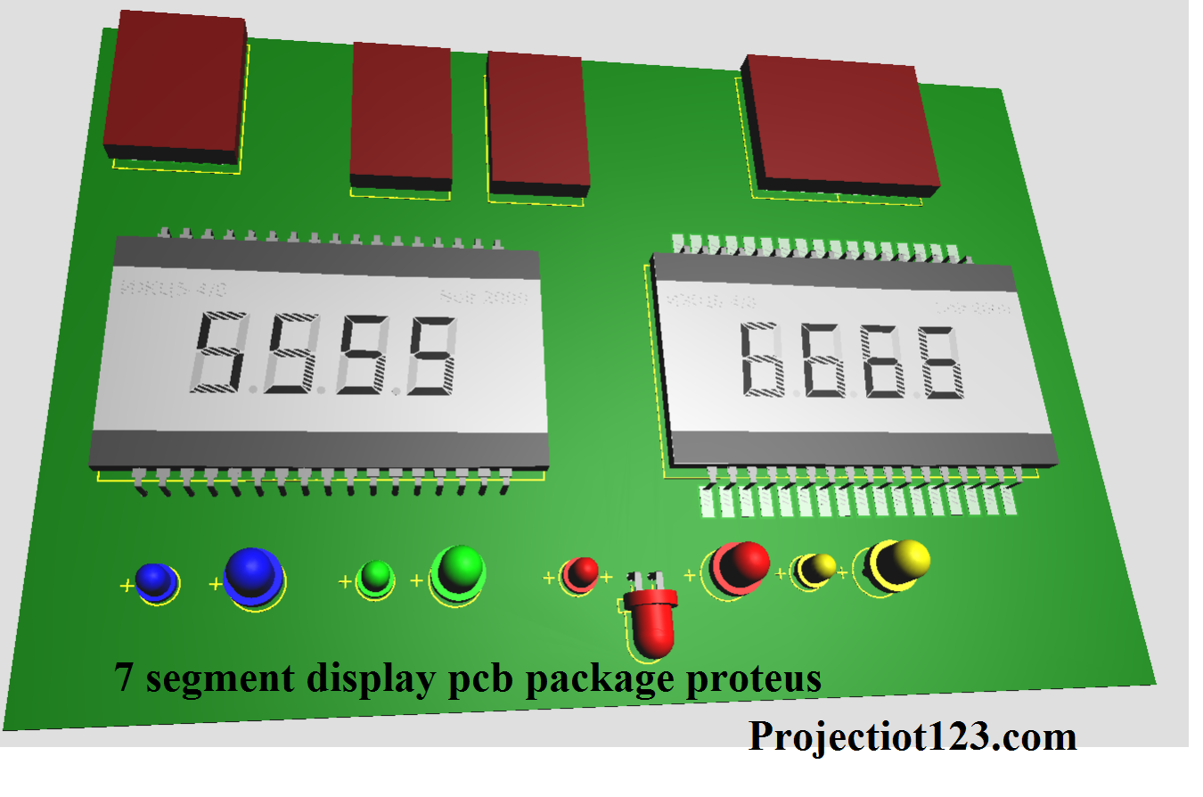
7 segment display pcb package proteus layout

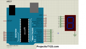
Seven Segment Display and Proteus:
After you have included the Seven Segment Display in the Proteus it’s now time to add the Arduino in the Proteus. This can also be done by searching for the Arduino in the Proteus and then double click to add Arduino in the Proteus workspace. Once you included both the Arduino and Seven Segment Display in the Proteus it will look like the one in the following image:
It is now time to write the code for the Arduino to drive the Seven Segment Display. At this point I have assumed that you have already installed the Arduino library for the Proteus.
[otw_is sidebar=otw-sidebar-2]
Arduino Code for Seven Segment Display:
Now open the Arduino IDE and write the code for driving the Seven Segment Display. You can simply copy and paste the code which I have written in the following:
void setup() {
// define pin modes
pinMode(2,OUTPUT);
pinMode(3,OUTPUT);
pinMode(4,OUTPUT);
pinMode(5,OUTPUT);
pinMode(6,OUTPUT);
pinMode(7,OUTPUT);
pinMode(8,OUTPUT);
}
void loop() {
// loop to turn leds od seven seg ON
for(int i=2;i<9;i++)
{ digitalWrite(i,HIGH);
delay(600);
}
// loop to turn leds od seven seg OFF
for(int i=2;i<9;i++)
{ digitalWrite(i,LOW);
delay(600);
}
delay(1000);
}
Circuit Assembling in Proteus:
After you have written the code assemble the circuit in the Proteus before compiling the code. The good thing is Arduino can supply enough current from its digital input/output pins to drive the Seven Segment Display so you do not need to insert any driving IC to drive the Segment Segment Display. The circuit after hooking up the Arduino with the Seven Segment Display looks like the one in the following figure:
Setting the HEX code in the Proteus:
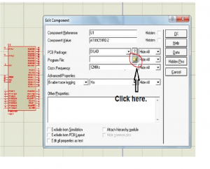
Now you need the HEX file for the code you have written in the Arduino IDE. This HEX file will be uploaded in the Proteus which will be ready for simulation. I have already discussed the about how to create HEX. I am repeating it
Open your Arduino IDE, click on the File, go into preferences and check the boxes with compilation and uploading.
[otw_is sidebar=otw-sidebar-3]
When you have check the boxes highlighted in the above write the code and then compile.
Once you have compiled the code by clicking the Verify button at the top left corner of the Arduino IDE. The Arduino IDE will automatically create the HEX file and give the link of it at the bottom.
Go to the link as specified by your Arduino IDE and you can find your HEX file there.
After you have made the HEX file it should be in some way given to the Proteus so that Proteus can use this HEX file to simulate the code and thus simulate the circuit. I am discussing here the steps for setting the HEX file in Proteus.
Open you Proteus.
Browse for the HEX file in the location where your newly created hex file is placed.
Finally click on the file and the hex file will be uploaded in the Proteus.
Now the Proteus is ready for simulating the Arduino circuit.
7 segment display arduino library
4 digit 7 segment displays use 12 digital i/o pins. You may need more pins if your display has colons or apostrophes.
you can Download sparkfun 7 segment library from here
4 seven segment display arduino in proteus
4 seven segment display arduino in proteus and up down counter using arduino
2 seven segment display arduino in proteus
pic microcontroller for beginners
This is all about today’s article Interfacing 7 Segment Display with Arduino in Proteus. I hope it would be helpful for you.
you can download from this proteus simulation